User’s Manual
Arctic IEC-104 Gateway
26
Viola Systems Ltd.
6. I/O Interface (optional)
This chapter describes the hardware and related software (for interface extensions).
There are two types of I/O boards:
IO-8-2
8 general purpose digital inputs, 2 digital outputs
IO-8-1-1
8 general purpose digital inputs, 1 digital output and 1 analog input for voltage
measurement or monitoring
Digital Inputs (IO-8-2 and IO-8-1-1 only)
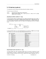
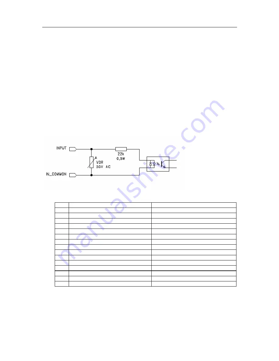
For general purpose digital I/O interfacing the Arctic includes eight digital inputs which all share a
common reference pin. The inputs are optically isolated and work with AC voltage levels from 5 to
60 V and this range is guaranteed to be interpreted as a logical high state. AC voltage levels less than
2 V are interpreted as a logical low state. The schematic of one digital input is shown in the figure
below.
In the figure
INPUT
refers to one of the eight
Digital Input n
-pins and
IN_COMMON
refers to
Digital
Input Common -
pin in the I/O connector’s pin description table shown below
.
Pin # 8-1-1 model
8-2 model (default)
1
DC out
DC out
2
Digital input 1
Digital input 1
3
Digital input 2
Digital input 2
4
Digital input 3
Digital input 3
5
Digital input 4
Digital input 4
6
Digital input 5
Digital input 5
7
Digital input 6
Digital input 6
8
Digital input 7
Digital input 7
9
Digital input 8
Digital input 8
10
Digital input common
Digital input common
11
Digital output 1A
Digital output 1A
12
Digital output 1B
Digital output 1B
13
Analog input 1+
Digital output 2A
14
Analog input 1-
Digital output 2B
15
DC GND
DC GND
Digital Outputs (IO-8-2 and IO-8-1-1 only)
The digital outputs of the Arctic are optically isolated and can be used for controlling low current
external devices. The output is a CMOS relay which is protected by a PTC type fuse. The output is
capable of handling a continuous current of 50 mA maximum at an ambient temperature of 20°C. In


