Manual VIPA System SLIO
Chapter 1 Basics and Assembly
HB300E - SM - Rev. 09/38
1-7
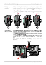
Installation
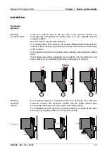
There is a locking lever at the top side of the terminal module. For
mounting and de-mounting this locking lever is to turn upwards until this
engages audible.
Now the module may be pulled forward.
For mounting plug the module to the module installed before and push the
module to the mounting rail guided by the strips at the upper and lower side
of the module.
The module is fixed to the mounting rail by pushing downwards the locking
lever.
The modules may either separately be mounted to the mounting rail or as
block. Here is to be considered that each locking lever is opened.
Clack
1
2
3
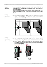
For mounting between 2 modules and for the exchange of a defective
electronic module, the electronic module may be pulled forward after
pressing the unlocking lever at the lower side of the module.
For installation plug the electronic module guided by the strips at the lower
side until this engages audible to the terminal module.
1. Press
2. Pull
Clack
Functional
principle
Mounting
terminal module
Mounting
electronic
module
Summary of Contents for 021-1BB00
Page 1: ...Manual VIPA System SLIO Signal modules SM Order No VIPA HB300E_SM Rev 09 38...
Page 2: ...L...
Page 6: ...Contents Manual VIPA System SLIO ii HB300E SM Rev 09 38...
Page 26: ...Chapter 1 Basics and Assembly Manual VIPA System SLIO 1 18 HB300E SM Rev 09 38...
Page 36: ...Chapter 2 Digital Input Manual VIPA System SLIO 2 10 HB300E SM Rev 09 38...
Page 44: ...Chapter 3 Digital Output Manual VIPA System SLIO 3 8 HB300E SM Rev 09 38...
Page 102: ...Chapter 5 Analog Output Manual VIPA System SLIO 5 24 HB300E SM Rev 09 38...


