background image

Chapter 4   Analog Input


Manual VIPA System SLIO 

4-26 


HB300E - SM - Rev. 09/38 

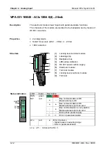
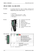
VIPA 031-1BD80 - AI 4x16Bit R/RTD 


The electronic module has 4 inputs for resistance measurement with 
parameterizable functions. The channels of the module are isolated to the 
backplane bus by means of DC/DC converters. 


• 

4 analog inputs 

• 

Suited for resistance-type sensors 0 ... 3000


• 

Resistance measurement with 2-, 3- and 4 wires 

• 

16bit resolution 


1

3

5

4

6

7
8

9

2


[1] 
[2] 
[3] 
[4] 
[5] 
[6] 
[7] 
[8] 
[9] 

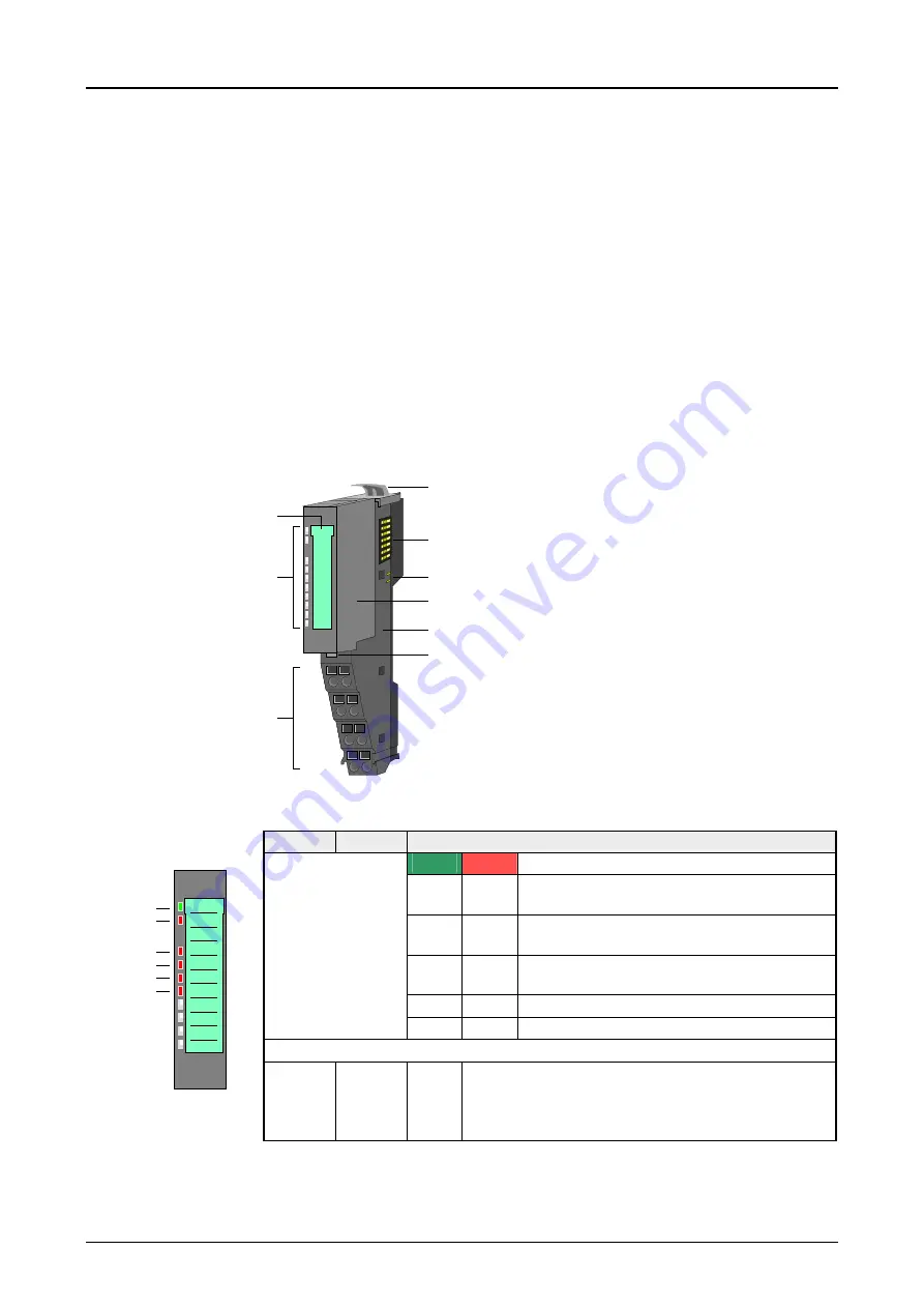
Locking lever terminal module 
Labeling strip 
Backplane bus 
LED status indication 
DC 24V power section supply 
Electronic module 
Terminal module 
Locking lever electronic module 
Terminal 


LED 

Color 

Description 

RUN green RUN

MF   

MF red 


Bus communication is OK  
Module status is OK 


Bus communication is OK 
Module status reports an error 


Bus communication is not possible 
Module status reports an error 


Error at bus power supply 


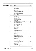
Error in parameterization  


Status indication 


RUN

MF

AI 0

AI 1

AI 2

AI 3


AI x 

red 


Error channel x 
- Signal leaves measuring range 
- Error in parameterization 
- Wire break 

on: 

   off: 

   blinks with 2Hz: 


Description 

Properties 

Structure 

Summary of Contents for 021-1BB00

Page 1: ...Manual VIPA System SLIO Signal modules SM Order No VIPA HB300E_SM Rev 09 38...

Page 2: ...L...

Page 3: ...ied with respect to the hard and software However we assume no responsibility for any discrepancies or errors The information in this manual is verified on a regular basis and any required corrections...

Page 4: ...a controller system consisting of System SLIO components Besides the dimensions the general technical data of System SLIO will be found Chapter 2 Digital input In this chapter you will find the descri...

Page 5: ...24V 2 8 Chapter 3 Digital Output 3 1 VIPA 022 1BB00 DO 2xDC 24V 0 5A 3 2 VIPA 022 1BD00 DO 4xDC 24V 0 5A 3 4 VIPA 022 1BF00 DO 8xDC 24V 0 5A 3 6 Chapter 4 Analog Input 4 1 General 4 2 Analog value 4 3...

Page 6: ...Contents Manual VIPA System SLIO ii HB300E SM Rev 09 38...

Page 7: ...ollowing guides are available in the manual an overall table of contents at the beginning of the manual an overview of the topics for every chapter The manual is available in printed form on paper in...

Page 8: ...ust be available to all personnel in the project design department installation department commissioning operation The following conditions must be met before using or commissioning the components des...

Page 9: ...find the information required to assemble and wire a controller system consisting of System SLIO components Besides the dimensions the general technical data of System SLIO will be found Topic Page Ch...

Page 10: ...onents thereby causing the module to become inoperable or unusable Modules that have been damaged by electrostatic discharges can fail after a temperature change mechanical shock or changes in the ele...

Page 11: ...section supply The System SLIO consists of the following components Bus coupler Periphery modules Power modules Accessories With a bus coupler bus interface and power module is integrated to one casin...

Page 12: ...periphery module is defined by the electronic module which is mounted to the terminal module by a save sliding mechanism With an error the defective module may be exchanged for a functional module wi...

Page 13: ...th the terminal of the terminal module With a flat mounting rail for adaption to a flat mounting rail you may remove the spacer of the shield bus carrier With each bus coupler to protect the backplane...

Page 14: ...Assembly Manual VIPA System SLIO 1 6 HB300E SM Rev 09 38 Dimensions 104 109 76 5 48 5 104 109 76 5 15 133 12 5 58 62 12 5 Dimensions in mm Dimensions bus coupler Dimensions periphery module Dimension...

Page 15: ...he module is fixed to the mounting rail by pushing downwards the locking lever The modules may either separately be mounted to the mounting rail or as block Here is to be considered that each locking...

Page 16: ...onsider that a clearance from the middle of the mounting rail of at least 80mm above and 60mm below respectively 80mm by deployment of shield bus carriers exist 80mm 80mm 60mm 65mm Start at the left s...

Page 17: ...now be mounted at the last module The shield bus carrier available as accessory serves to carry the shield bus to connect cable shields The shield bus carrier is mounted underneath the terminal of th...

Page 18: ...at both sides to the mounting rail 1 2 3 4 With mounting respectively de mounting of a module group you also have to remove the electronic module of the just mounted right module After mounting it may...

Page 19: ...c power supply bus coupler and I O area Note Power section and electronic power section supply are internally protected against higher voltage by fuses The fuses are within the power module If one fus...

Page 20: ...you have also the possibility to define isolated groups The following figure should illustrate the usage of the power modules 007 1AB00 Sys DC 5V DC 24V 10A 007 1AB00 Sys DC 5V DC 24V 10A DC24V 0V DC...

Page 21: ...The shield bus carrier is mounted underneath the terminal of the terminal module With a flat mounting rail for adaption to a flat mounting rail you may remove the spacer of the shield bus carrier Aft...

Page 22: ...cing the environment All System SLIO components are developed for the deployment in hard industrial environments and fulfill high demands on the EMC Nevertheless you should project an EMC planning bef...

Page 23: ...s must be laid isolated When transmitting signals with small amplitudes the one sided laying of the isolation may be favorable Lay the line isolation extensively on an isolation protected earth con du...

Page 24: ...ne sided Then you only achieve the absorption of the lower frequencies A one sided isolation connection may be convenient if the conduction of a potential compensating line is not possible analog sign...

Page 25: ...rage transport EN 60068 2 14 25 70 C Operation Horizontal installation EN 61131 2 0 60 C Vertical installation EN 61131 2 0 55 C Air humidity EN 60068 2 30 RH1 without condensation rel humidity 10 95...

Page 26: ...Chapter 1 Basics and Assembly Manual VIPA System SLIO 1 18 HB300E SM Rev 09 38...

Page 27: ...ut In this chapter you will find the description of the digital input modules of the System SLIO from VIPA Topic Page Chapter 2 Digital Input 2 1 VIPA 021 1BB00 DI 2xDC 24V 2 2 VIPA 021 1BD00 DI 4xDC...

Page 28: ...electronic power supply 1 3 5 4 6 7 8 9 2 1 2 3 4 5 6 7 8 9 Locking lever terminal module Labeling strip Backplane bus LED status indication DC 24V power section supply Electronic module Terminal mod...

Page 29: ...4 not connected 5 DI 1 I Digital input DI 1 6 DC 24V O DC 24V for sensor 7 0V O GND 8 not connected I Input O Output Data VIPA 021 1BB00 Number of inputs 2 Nominate input voltage DC 24V 20 4 28 8V Sig...

Page 30: ...tronic power supply 1 3 5 4 6 7 8 9 2 1 2 3 4 5 6 7 8 9 Locking lever terminal module Labeling strip Backplane bus LED status indication DC 24V power section supply Electronic module Terminal module L...

Page 31: ...DC 24V for sensor 5 DI 1 I Digital input DI 1 6 DC 24V O DC 24V for sensor 7 DI 3 I Digital input DI 3 8 DC 24V O DC 24V for sensor I Input O Output Data VIPA 021 1BD00 Number of inputs 4 Nominate inp...

Page 32: ...activated electronic power supply 1 3 5 4 6 7 8 9 2 1 2 3 4 5 6 7 8 9 Locking lever terminal module Labeling strip Backplane bus LED status indication DC 24V power section supply Electronic module Te...

Page 33: ...igital input DI 2 5 DI 1 I Digital input DI 1 6 DC 24V O DC 24V for sensor 7 0V O GND 8 DI 3 I Digital input DI 3 I Input O Output Data VIPA 021 1BD40 Number of inputs 4 Nominate input voltage DC 24V...

Page 34: ...er supply 1 3 5 4 6 7 8 9 2 1 2 3 4 5 6 7 8 9 Locking lever terminal module Labeling strip Backplane bus LED status indication DC 24V power section supply Electronic module Terminal module Locking lev...

Page 35: ...DI 4 4 DI 6 I Digital input DI 6 5 DI 1 I Digital input DI 1 6 DI 3 I Digital input DI 3 7 DI 5 I Digital input DI 5 8 DI 7 I Digital input DI 7 I Input Data VIPA 021 1BF00 Number of inputs 8 Nominate...

Page 36: ...Chapter 2 Digital Input Manual VIPA System SLIO 2 10 HB300E SM Rev 09 38...

Page 37: ...9 38 3 1 Chapter 3 Digital Output The digital output modules of the System SLIO will be found here Topic Page Chapter 3 Digital Output 3 1 VIPA 022 1BB00 DO 2xDC 24V 0 5A 3 2 VIPA 022 1BD00 DO 4xDC 24...

Page 38: ...module Labeling strip Backplane bus LED status indication DC 24V power section supply Electronic module Terminal module Locking lever electronic module Terminal LED Color Description RUN green RUN MF...

Page 39: ...O 1 6 DC 24V O DC 24V 7 0V O GND for actuator 8 not connected O Output Data VIPA 022 1BB00 Number of outputs 2 Nominal load voltage DC 24V 20 4 28 8V Current consumption 5V 24V 55mA 5mA load Isolation...

Page 40: ...e Labeling strip Backplane bus LED status indication DC 24V power section supply Electronic module Terminal module Locking lever electronic module Terminal LED Color Description RUN green RUN MF MF re...

Page 41: ...DO 1 6 0V O GND for actuator DO 1 7 DO 3 O Digital output DO 3 8 0V O GND for actuator DO 3 O Output Data VIPA 022 1BD00 Number of outputs 4 Nominal load voltage DC 24V 20 4 28 8V Current consumption...

Page 42: ...strip Backplane bus LED status indication DC 24V power section supply Electronic module Terminal module Locking lever electronic module Terminal LED Color Description RUN green RUN MF MF red Bus comm...

Page 43: ...l output DO 1 6 DO 3 O Digital output DO 3 7 DO 5 O Digital output DO 5 8 DO 7 O Digital output DO 7 O Output Data VIPA 022 1BF00 Number of outputs 8 Nominal load voltage DC 24V 20 4 28 8V Current con...

Page 44: ...Chapter 3 Digital Output Manual VIPA System SLIO 3 8 HB300E SM Rev 09 38...

Page 45: ...es the description of the analog input modules of the System SLIO will be found here Topic Page Chapter 4 Analog Input 4 1 General 4 2 Analog value 4 3 Measuring ranges 4 4 VIPA 031 1BB30 AI 2x12Bit 0...

Page 46: ...sensors may be connected to the analog input modules Current sensor Voltage sensor Resistance type sensors Temperature sensors Note Please take care of the correct polarity when installing the sensors...

Page 47: ...Measuring value 0 0 0 15bit sign SG Measuring value With a resolution of 12bit plus sign bit the not used low value positions 3bits are filled with 0 The algebraic sign bit is represented by bit 15 H...

Page 48: ...nderrange 10 16384 U D 16384 10 D U Measuring range function number Current I Decimal D Hex Range Formulas for calculation 23 52 32511 7EFFh overrange 20mA 27648 6C00h 10mA 13824 3600h 0mA 0 0000h nom...

Page 49: ...C 2000 8500 nominal range 3 wire PT1000 59h 243 C 2430 underrange 295 C 2950 overrange 60 250 C 600 2500 nominal range 3 wire NI100 5Ah 105 C 1050 underrange 295 C 2950 overrange 60 250 C 600 2500 no...

Page 50: ...rrange overrange 0 3000 0 32767 nominal range 4 wire 0 3000 82h underrange overrange 0 60 0 6000 nominal range 2 wire 0 60 90h underrange overrange 0 600 0 6000 nominal range 2 wire 0 600 91h underran...

Page 51: ...0 3000 0 27648 nominal range 2 wire 0 3000 D2h underrange 70 55 32511 overrange 0 60 0 27648 nominal range 3 wire 0 60 D8h underrange 705 5 32511 overrange 0 600 0 27648 nominal range 3 wire 0 600 D9...

Page 52: ...Labeling strip Backplane bus LED status indication DC 24V power section supply Electronic module Terminal module Locking lever electronic module Terminal LED Color Description RUN green RUN MF MF red...

Page 53: ...wing there are the measuring ranges with function number listed which were supported by the analog module With FFh the corresponding channel is deactivated The formulas listed here allow you to transf...

Page 54: ...input 72h digital output 73h analog output 74h analog in output Bit 7 reserved 71h 5 Number of diagnostic output bits per channel 08h 6 Number of similar channels of a module 02h 7 Bit 0 channel error...

Page 55: ...nge 0 10V Current consumption 5V 24V 70mA 15mA Internal resistor 100k Limit frequency input filter 1kHz Resolution 12bit Conversion time 2ms all channels Measuring error 0 2 relating to operational li...

Page 56: ...odule Labeling strip Backplane bus LED status indication DC 24V power section supply Electronic module Terminal module Locking lever electronic module Terminal LED Color Description RUN green RUN MF M...

Page 57: ...ction Type Description 1 AI 0 I Channel 0 2 AI 0 I Ground Channel 0 3 not connected 4 not connected 5 AI 1 I Channel 1 6 AI 1 I Ground Channel 1 7 not connected 8 not connected I Input The parameter d...

Page 58: ...0h 0mA 0 0000h nominal range 0 20mA Siemens S7 format 31h 3 52 4864 ED00h underrange 20 27648 I D 27648 20 D I 25 00mA 20480 5000h overrange 20mA 16384 4000h 10mA 8192 2000h 0mA 0 0000h nominal range...

Page 59: ...input 72h digital output 73h analog output 74h analog in output Bit 7 reserved 71h 5 Number of diagnostic output bits per channel 08h 6 Number of similar channels of a module 02h 7 Bit 0 channel error...

Page 60: ...20mA Current consumption 5V 24V 70mA 15mA Internal resistor 110k Limit frequency input filter 1kHz Resolution 12bit Conversion time 2ms all channels Measuring error 0 20mA 0 2 4 20mA 0 3 relating to o...

Page 61: ...ling strip Backplane bus LED status indication DC 24V power section supply Electronic module Terminal module Locking lever electronic module Terminal LED Color Description RUN green RUN MF MF red Bus...

Page 62: ...10h 131 0 Function number channel 3 10h In the following there are the measuring ranges with function number listed which were supported by the analog module With FFh the corresponding channel is dea...

Page 63: ...error channel 0 Bit 1 channel error channel 1 Bit 2 channel error channel 2 Bit 3 channel error channel 3 Bit 7 4 reserved 00h 8 Channel specific error channel 0 Bit 0 configuring parameter assignment...

Page 64: ...nge 0 10V Current consumption 5V 24V 70mA 15mA Internal resistor 100k Limit frequency input filter 1kHz Resolution 12bit Conversion time 4ms all channels Measuring error 0 2 relating to operational li...

Page 65: ...Labeling strip Backplane bus LED status indication DC 24V power section supply Electronic module Terminal module Locking lever electronic module Terminal LED Color Description RUN green RUN MF MF red...

Page 66: ...I 0 I Ground Channel 0 3 AI 2 I Channel 2 4 AI 2 I Ground Channel 2 5 AI 1 I Channel 1 6 AI 1 I Ground Channel 1 7 AI 3 I Channel 3 8 AI 3 I Ground Channel 3 I Input The parameter data may be accessed...

Page 67: ...0h 0mA 0 0000h nominal range 0 20mA Siemens S7 format 31h 3 52 4864 ED00h underrange 20 27648 I D 27648 20 D I 25 00mA 20480 5000h overrange 20mA 16384 4000h 10mA 8192 2000h 0mA 0 0000h nominal range...

Page 68: ...error channel 0 Bit 1 channel error channel 1 Bit 2 channel error channel 2 Bit 3 channel error channel 3 Bit 7 4 reserved 00h 8 Channel specific error channel 0 Bit 0 configuring parameter assignment...

Page 69: ...20mA Current consumption 5V 24V 70mA 15mA Internal resistor 110k Limit frequency input filter 1kHz Resolution 12bit Conversion time 4ms all channels Measuring error 0 20mA 0 2 4 20mA 0 3 relating to o...

Page 70: ...9 Locking lever terminal module Labeling strip Backplane bus LED status indication DC 24V power section supply Electronic module Terminal module Locking lever electronic module Terminal LED Color Desc...

Page 71: ...mm2 2 6 3 7 4 8 1 5 1 2 3 4 5 6 7 8 2 6 3 7 4 8 1 5 AI DC24V 0V AI 1 2 3 4 5 6 7 8 0 1 2 3 Pos Function Type Description 1 AI 0 I Channel 0 2 AI 0 I Ground Channel 0 3 AI 2 I Channel 2 4 AI 2 I Ground...

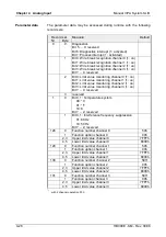
Page 72: ...3 Limit value monitoring channel 3 1 on Bit 7 4 reserved 3 reserved 1 0 Bit 0 1 Temperature system 00 C 01 F 10 K Bit 7 2 reserved 1 Bit 0 1 Interference frequency suppression 01 60Hz 10 50Hz Bit 7 2...

Page 73: ...2 04h 24 2 20 5 05h 14 2 12 2 06h 9 2 8 0 07h 6 6 5 9 08h 4 2 3 8 For each channel an upper and a lower limit may be defined As soon as the measuring value is be beyond the limits and the limit value...

Page 74: ...0 8500 nominal range 3 wire PT1000 59h 243 C 2430 underrange 295 C 2950 overrange 60 250 C 600 2500 nominal range 3 wire NI100 5Ah 105 C 1050 underrange 295 C 2950 overrange 60 250 C 600 2500 nominal...

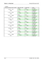
Page 75: ...ange overrange 0 3000 0 32767 nominal range 4 wire 0 3000 82h underrange overrange 0 60 0 6000 nominal range 2 wire 0 60 90h underrange overrange 0 600 0 6000 nominal range 2 wire 0 600 91h underrange...

Page 76: ...0 3000 0 27648 nominal range 2 wire 0 3000 D2h underrange 70 55 32511 overrange 0 60 0 27648 nominal range 3 wire 0 60 D8h underrange 705 5 32511 overrange 0 600 0 27648 nominal range 3 wire 0 600 D9h...

Page 77: ...r channel 2 Bit 3 channel error channel 3 Bit 7 4 reserved 00h 8 Channel specific error channel 0 Bit 0 configuring parameter assignment error Bit 3 1 reserved Bit 4 wire break Bit 5 reserved Bit 6 me...

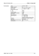
Page 78: ...stor 0 3000 Current consumption 5V 24V 75mA 30mA Internal resistor min 10M Resolution 16bit Conversion time 4 2 324 1ms each channel at 50Hz 3 8 270 5ms each channel at 60Hz Measuring error 0 3 relati...

Page 79: ...the output ranges the description of the analog output modules of the System SLIO will be found here Topic Page Chapter 5 Analog Output 5 1 General 5 2 Analog value 5 3 Output ranges 5 4 VIPA 032 1BB3...

Page 80: ...f the signal cable at one end only You can use the analog output modules to supply loads and actuators with current or voltage Note Please take always care of the correct polarity when connecting actu...

Page 81: ...Resolution Analog value High byte byte 0 Low byte byte 1 Bit number 15 14 13 12 11 10 9 8 7 6 5 4 3 2 1 0 Resolution SG 214 213 212 211 210 29 28 27 26 25 24 23 22 21 20 12bit SG SG Analog value word...

Page 82: ...16384 10 D U 10 16384 U D Output range function number Current I Decimal D Hex Range Formulas for calculation 23 49 32511 7EFFh overrange 20mA 27648 6C00 10mA 13824 3600 0mA 0 0 nominal range 0 20mA...

Page 83: ...dule Labeling strip Backplane bus LED status indication DC 24V power section supply Electronic module Terminal module Locking lever electronic module Terminal LED Color Description RUN green RUN MF MF...

Page 84: ...nel 0 10h 129 0 Function number channel 1 10h In the following there are the measuring ranges with function number listed which were supported by the analog module With FFh the corresponding channel i...

Page 85: ...nput 71h analog input 72h digital output 73h analog output 74h analog in output Bit 7 reserved 73h 5 Number of diagnostic output bits per channel 08h 6 Number of similar channels of a module 02h 7 Bit...

Page 86: ...le Input range 0 10V Current consumption 5V 24V 80mA 35mA Burden min 5k short circuit proof Accuracy 0 2 relating to operational limit at 25 C Resolution 12bit incl overrange area Conversion time 2ms...

Page 87: ...dule Labeling strip Backplane bus LED status indication DC 24V power section supply Electronic module Terminal module Locking lever electronic module Terminal LED Color Description RUN green RUN MF MF...

Page 88: ...channels 3 not connected 4 not connected 5 AO 1 O Channel 1 6 AGND O Ground channels 7 not connected 8 not connected O Output The parameter data may be accessed during runtime with the following recor...

Page 89: ...mA 0 0 nominal range 0 20mA Siemens S7 format 31h Not possible is limited to 0mA underrange 27648 20 D I 20 27648 I D 25 00mA 20480 5000h overrange 20mA 16384 4000 10mA 8192 2000 0mA 0 0 nominal range...

Page 90: ...70h digital input 71h analog input 72h digital output 73h analog output 74h analog in output Bit 7 reserved 73h 5 Number of diagnostic output bits per channel 08h 6 Number of similar channels of a mod...

Page 91: ...ange 0 20mA 4 20mA Current consumption 5V 24V 80mA 15mA without load Burden max 350 Accuracy 0 20mA 0 2 4 20mA 0 3 relating to operational limit at 25 C Resolution 12bit incl overrange area Conversion...

Page 92: ...Labeling strip Backplane bus LED status indication DC 24V power section supply Electronic module Terminal module Locking lever electronic module Terminal LED Color Description RUN green RUN MF MF red...

Page 93: ...7 AO 3 O Channel 3 8 AGND O Ground channels O Output The parameter data may be accessed during runtime with the following record sets Record set No Byte Meaning Default 0 1 Bit 0 Short circuit recogn...

Page 94: ...a value assigned to the measuring range analog value and vice versa Output range function number Voltage U Decimal D Hex Range Formulas for calculation 11 76 32511 7EFFh overrange 10V 27648 6C00h 5V...

Page 95: ...of a module 04h 7 Bit 0 channel error channel 0 Bit 1 channel error channel 1 Bit 2 channel error channel 2 Bit 3 channel error channel 3 Bit 7 4 reserved 00h 8 Channel specific error channel 0 Bit 0...

Page 96: ...le Input range 0 10V Current consumption 5V 24V 80mA 35mA Burden min 5k short circuit proof Accuracy 0 2 relating to operational limit at 25 C Resolution 12bit incl overrange area Conversion time 2ms...

Page 97: ...strip Backplane bus LED status indication DC 24V power section supply Electronic module Terminal module Locking lever electronic module Terminal LED Color Description RUN green RUN MF MF red Bus commu...

Page 98: ...annels 7 AO 3 O Channel 3 8 AGND O Ground channels O Output The parameter data may be accessed during runtime with the following record sets Record set No Byte Meaning Default 0 0 Bit 0 Wire break rec...

Page 99: ...mA 0 0 nominal range 0 20mA Siemens S7 format 31h Not possible is limited to 0mA underrange 27648 20 D I 20 27648 I D 25 00mA 20480 5000h overrange 20mA 16384 4000 10mA 8192 2000 0mA 0 0 nominal range...

Page 100: ...umber of similar channels of a module 04h 7 Bit 0 channel error channel 0 Bit 1 channel error channel 1 Bit 2 channel error channel 2 Bit 3 channel error channel 3 Bit 7 4 reserved 00h 8 Channel speci...

Page 101: ...ange 0 20mA 4 20mA Current consumption 5V 24V 80mA 15mA without load Burden max 350 Accuracy 0 20mA 0 2 4 20mA 0 3 relating to operational limit at 25 C Resolution 12bit incl overrange area Conversion...

Page 102: ...Chapter 5 Analog Output Manual VIPA System SLIO 5 24 HB300E SM Rev 09 38...

Reviews: