background image

Chapter 2   Deployment Touch Panel


Manual VIPA HMI 

2-14 


HB160E - TP - RE_605-1BC00 - Rev. 08/13 

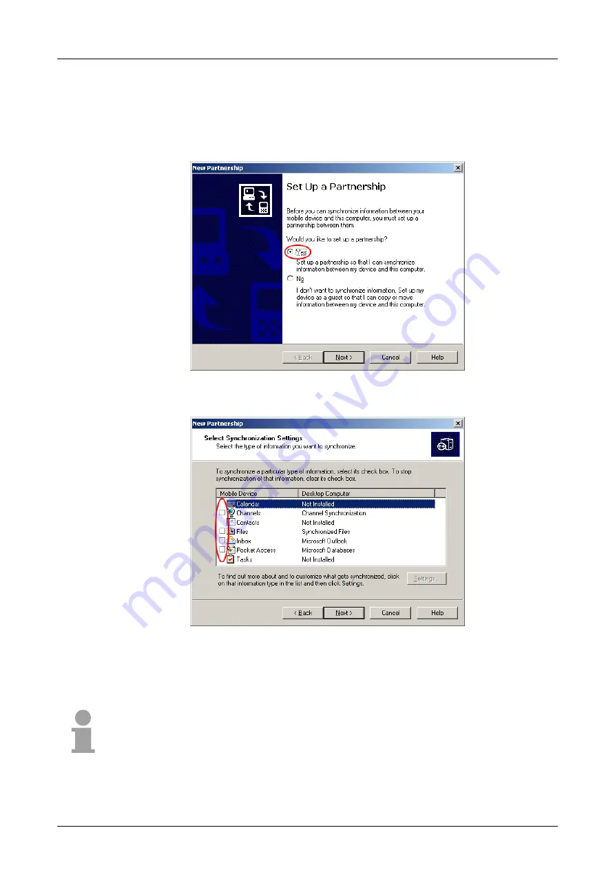
Now you may install a "partnership" via an USB connection with the 
following approach: 

• 

Connect your Touch Panel via the "Device"-USB-B jack with your PC 
and turn on the Touch Panel. 

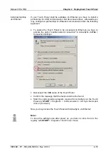
 The USB device (Touch Panel) is 

recognized and the dialog window "new partnership" opens. 


• 

Choose "yes" that you want to fix a partnership and push [Next]. 

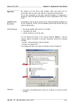
• 

In the now opening window, de-activate all synchronization settings and 
click on [Next]: 


• 

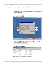
[Finish] establishes the partnership. 


Now you may access the Touch Panel with ActiveSync via USB. 


Note! 

To keep the settings also after power on, you have to store them to the 
registry with 

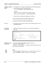
START

 > 

Programs

 > 

KuK Tools

 > 

Save Registry

Install partnership 
for USB communi-
cation 


Summary of Contents for 605-1BC00

Page 1: ...Order no VIPA HB160E_TP Reference RE_605 1BC00 Rev 08 13 This manual is part of the documentation package with order number VIPA HB160E_TP and relevant for Product Order number as of state HW OS TP 60...

Page 2: ...Lerrzeichen...

Page 3: ...nsure that it conforms with the described hardware and software However discrepancies can not be avoided The specifications in this manual are examined regularly and corrections will be included in su...

Page 4: ...so find the dimensions that are required for the installation The chapter closes with the technical data Chapter 2 Deployment Touch Panel This chapter deals with the employment of the Touch Panel At t...

Page 5: ...sioning 2 4 Connection to a PLC system 2 6 Operating system Windows CE 2 7 Communication via ActiveSync 2 13 Integrated Server 2 16 Access to the network resources 2 23 Integration to WLAN network 2 2...

Page 6: ...Contents Manual VIPA HMI ii HB160E TP RE_605 1BC00 Rev 08 13...

Page 7: ...ter An index at the end of the manual The manual is available in printed form on paper in electronic form as PDF file Adobe Acrobat Reader Button Buttons are put in brackets e g NEXT or OK Key Key ent...

Page 8: ...nual must be available to all personnel in the project design department installation department commissioning operation The following conditions must be met before using or commissioning the componen...

Page 9: ...l TP 605CQ from VIPA Besides of a description of the single components of the Touch Panel you will also find the dimensions that are required for the installation The chapter closes with the technical...

Page 10: ...reby causing the module to become inoperable or unusable Modules that have been damaged by electrostatic discharges may fail after a temperature change mechanical shock or changes in the electrical lo...

Page 11: ...uitable for monitoring and controlling of process cycles Microsoft Windows CE V 5 0 full version as option different HMI SCADA Runtime selectable about 6MByte memory for user data on Board CF Card II...

Page 12: ...1 Slot for storage medium CF SD MMC 2 Connection for interfaces and power supply T o u c h P a n e l 1 2 3 3 Display with touch sensitive area touch screen 1 Compact Flash 2 MMC SD 1 2 Note Please reg...

Page 13: ...B A interface 5 Slave USB B interface 6 RJ45 jack for Ethernet communication 7 Slot for DC 24V voltage supply 8 Slot for CF SD MMC storage medium Note Please regard the functionality of the interface...

Page 14: ...vice Slot for CF Here you may plug a CompactFlash type II The card may be plugged and removed during runtime and is immediately listed as Storage Card at My Device Every CompactFlash storage module ha...

Page 15: ...22 Periphery 3 8 4 9 M5V TxD TxD RxD RxD P5V 5 6 Connection RS485 isolated Note Please regard the functionality of the interface depends to the hardware version HW 01 RS422 functionality HW 02 RS485 f...

Page 16: ...er rate up to 115 2kBaud 9pin plug Connection RS232 Pin RS232 1 CD 2 RxD 3 TxD 4 DTR 5 GND 6 DSR 7 RTS 8 CTS 1 2 3 4 5 6 7 8 9 9 RI RxD TxD GND TxD RxD 3 2 GND 5 RTS CTS 7 8 Shield RS232 Periphery Shi...

Page 17: ...nt is as follows Slave USB B Pin Assignment 1 VCC 2 DM 3 DP 2 1 3 4 4 GND The USB A interface of your PC can be connected to the Slave USB B interface of your Touch Panel deploying the USB programming...

Page 18: ...ary Installation cutting W x H 200 x 144mm Front panel W x H 212 x 156mm Installation depth 37mm Note The degrees of protection are only guaranteed when the following is observed Material thickness at...

Page 19: ...Operating temperature 0 50 C Relative humidity max 85 Storing Transport temperature 20 to 60 C Display Size 5 7 Resolution 240 x 320 320 x 240 Colors TFT color 64K colors MTBF Backlights 25 C ca 50000...

Page 20: ...Chapter 1 Hardware description Manual VIPA HMI 1 12 HB160E TP RE_605 1BC00 Rev 08 13...

Page 21: ...connection of the Touch Panel The main part of the chapter introduces Windows CE and the various communication options offered by the Touch Panel Topic Page Chapter 2 Deployment Touch Panel 2 1 Instal...

Page 22: ...le For the installation into a operating tableau and control cabinet fronts the Touch Panel requires the following front plate cutting W H Touch Panel W x H in mm 606 1BC00 200 x 144 The fixing techni...

Page 23: ...e flexible wires without end case as well as stiff wires You fix the conductors to the CageClamps like this DC 24V 1 2 3 1 Round opening for wires 2 Locking orange for screwdriver 3 Test point for 2mm...

Page 24: ...Panel is provided by power supply the Touch Panel starts with the VIPA Startup Manager The VIPA Startup Manager has the following buttons A project is started within the VIPA Startup Manager after a c...

Page 25: ...zation software is used LOCATION Indicates the file location of the visualization software FILE Path and file name of the last started project FONT Indicates the storage location of additional fonts t...

Page 26: ...led runtime version of the HMI SCADA project engineering platforms your project is run able By using the according communication driver the Touch Panel supports connecting options to the PLC via MPI f...

Page 27: ...ed to the absolute essentials with mouse operation touch screen that requires only small hardware resources Here the 2 icons My Device and Recycle Bin may exclusively be found at the Desktop The Profe...

Page 28: ...selects the touched objects Characteristics with Windows CE Professional Plus V 5 0 In the Professional Plus version mouse functions are fully supported As soon as the touch screen is touched with the...

Page 29: ...tings file browser etc 2 Open applications For every open application a button is to be found in the task bar There is no button for minimizing The switch between the applications happens via this but...

Page 30: ...clusively entered via the software keyboard Keyboard Normal At pushed SHIFT key Meaning Home Position 1 End End BS Backspace up dn lt rt pgup Page pgdn Page ins Insert del Delete Tab Tabulator Shift C...

Page 31: ...ou may use the grid pattern to preset a double click velocity and test this on the symbol below OK takes over the set value The calibration of the touch screens happens via the register Calibration by...

Page 32: ...or the Touch Panel Baud Rate Enter here the transfer velocity of your MPI net The baud rate has to be identical for every MPI participant within the network According to the Baud Rate the network para...

Page 33: ...Panel from the PC via ActiveSync you have to install it at the PC ActiveSync is freeware and may be downloaded from www microsoft de Download the ActiveSync from the Microsoft website and start the fi...

Page 34: ...ouch Panel is recognized and the dialog window new partnership opens Choose yes that you want to fix a partnership and push Next In the now opening window de activate all synchronization settings and...

Page 35: ...ernet you have to activate the option enable network connection in ActiveSync via File Connection Settings Disconnect the USB cable of the Touch Panel Confirm the message that the device could not be...

Page 36: ...via START Programs KuK Tools before switching off Per default the following server are integrated ftp server activated http server activated Telnet activated VNC not activated Phrases that are used in...

Page 37: ...ns for an ftp connection If there are still problems with the ftp access ask your system administrator ftp access possible with version 5 5 or higher use passive ftp mode activate directory view for f...

Page 38: ...nnect your Touch Panel with the network where your PC is a member via an Ethernet cable Switch on your Touch Panel As soon as your Touch Panel is connected via Ethernet you may monitor the IP address...

Page 39: ...into the address bar IP address webadmin Enter the following into the authentification User name wince Password vipatp Remember to store your changes permanently in the registry via Start Programs KuK...

Page 40: ...plication is not possible The establishing of a Telnet connection is password protected and has the following approach Start a Telnet client like for example MS DOS console at your PC and enter the fo...

Page 41: ...Rev 08 13 2 21 After establishment of a Telnet connection the Touch Panel provides you with commands A list of possible commands with a short description is available via the command help By beginnin...

Page 42: ...ely for start up For this reason the VNC server is on delivery deactivated The VNC connection establishment has the following approach Click on at the Touch Panel and start Windows CEVncSvr exe Please...

Page 43: ...test the physical connection a PING to the IP address of the network PC may be executed if there are problems while contacting the network PC The connection of a local name at the Touch Panel with a...

Page 44: ...etwork printer For example you may print the content of the current directory with dir network printer The listing of all network connections of your Touch Panel happens via net use You may terminate...

Page 45: ...s is opened Continue with WLAN integration Please regard only WLAN USB sticks are supported with the chip of the company Funkwerk inside PowerOFF the Touch Panel Plug the WLAN USB stick to the USB A i...

Page 46: ...tivated For this open the register Wireless Information in the dialog window and click to the Advanced button The following window is shown By activating of Automatically connect to non preferred netw...

Page 47: ...sed Switch off the power supply from your panel Plug the memory card to your panel and switch on the power supply again As soon as a new firmware is found at the memory card it is downloaded to the To...

Page 48: ...Chapter 2 Deployment Touch Panel Manual VIPA HMI 2 28 HB160E TP RE_605 1BC00 Rev 08 13...

Page 49: ...Here we describe possible paths in which interference can enter the controller how you ensure the electromagnetic compatibility EMC and how to approach shielding and screening issues Topic Page Chapte...

Page 50: ...industrial environments and complies with EMC requirements to a large degree In spite of this you should implement an EMC strategy before installing any components which should include any possible s...

Page 51: ...te to the time wise change of the voltage Interference through parallel signal lines Static discharge of the personnel Contactors Inductive coupling Automation System Disruptor inductive coupling line...

Page 52: ...groups High voltage lines power supply lines signal lines data lines Always install high voltage lines and signal or data lines in separate channels or bundles Install signal and data lines as close...

Page 53: ...cent lamps Create a single reference potential and ensure that all electrical equipment is grounded wherever possible Ensure that grounding measures are implemented effectively The controllers are ear...

Page 54: ...may only get voltage in case of an error The ground must not adopt dangerous contact voltage even in case of an error Thus you have to connect the ground with the protected earth conductor To avoid gr...

Page 55: ...to divide the cables in different groups and install each group itself Group A screened bus and data lines screened analog lines unshielded lines for direct voltage 60V unshielded lines for alternatin...

Page 56: ...be installed on metallic cable trays A galvanic connection must be provided for joints between cable trays You must abide by the applicable lightning protection and grounding regulations when install...

Page 57: ...mm 2 Cu for equipotential bonding conductors up to 200m 25mm2 Cu for equipotential bonding conductors exceeding 200m Use copper or galvanized steel for equipotential bonding conductors These must be c...

Page 58: ...recommended that the remove the insulation from the screened cable without cutting the screen and to attach this point to the screening neutral rail Note Potential differences can give rise to an equ...

Page 59: ...uctors Connections of DC activated inductors Connections of AC activated inductors using a diode using a Z diode using a varistor using RC network Every cubicle must be provided with a power outlet fo...

Page 60: ...l contact washer Have the connection been protected from corrosion e g by means of grease Have doors been grounded by means of grounding straps connected to the body of the cubicle Cable routing Cabli...

Page 61: ...er 2 17 H http server 2 19 I Installation 2 2 cutting 2 2 guidelines 3 1 L Login data 2 16 M Memory management 1 6 MMC 1 6 MPI interface 1 7 MPI parameters 2 12 N net use 2 23 net view 2 23 Network Ac...

Page 62: ...Index Manual VIPA HMI A 2 HB160E TP RE_605 1BC00 Rev 08 13 M Stich...

Reviews: