Manual VIPA Accessories
Chapter 3
Hardware description
HB37E - IM - RE_306-1LE00 - Rev. 09/28
3-3
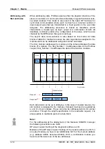
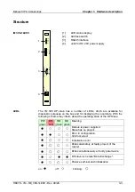
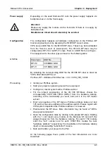
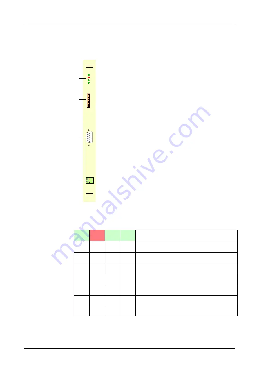
Structure
[1]
LED status display
[2] Address
switch
[3] RS485
interface
[4]
Jack for DC 24V power supply
64
32
16
8
4
2
1
-
1
0
PW
ER
RD
DE
A
D
R
P
B
-
D
P
1
2
3
4
DC
24V
| V
IP
A
| 3
06
-1
LE
00
|
M
|1
|2
|3
|4
|5
|6
|7
|8
|9
|1
0
|
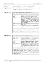
The IM 306 DP slave has a number of LEDs, which are available for
diagnostic purposes on the bus and for displaying the local state. With the
following scheme they inform about the operating state of the DP Slave:
PW
green
ER
red
RD
green
DE
green
Meaning
●
○
○
○
Module is power supplied.
Slave has no project.
●
●
○
○
Error in configuration.
QVZ occurred.
●
☼
○
○
Initialization error
●
☼
☼
○
Blinks alternately at faulty project of the
master.
●
☼
☼
○
Blinks simultaneously at faulty parameters.
●
○
●
●
DP slave is in state "Data Exchange".
●
○
☼
○
Positive self-test and initialization
on:
●
off:
○
blinking:
☼
IM 306-1LE00
LEDs


