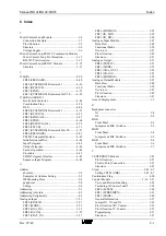
Index
Manual BG41/BG42/BG43
C-2
Rev. 99/49
D
DCF77 Antenna Module......................................... 3-74
Alignment of the Antenna .................................. 3-79
Connection Example .......................................... 3-79
Dimensions ........................................................ 3-76
Installation on a SSM-BG .................................. 3-81
LED Description ................................................ 3-80
Location of Transmitter ..................................... 3-75
Pin Allocation .................................................... 3-77
Reset .................................................................. 3-80
Start-up Response .............................................. 3-80
Structure............................................................. 3-74
Time Plan........................................................... 3-77
Diagnostic Interface................................................ 5-19
Piece of advice................................................... 5-19
DIL Switches .......................................................... 5-11
Position .............................................................. 5-11
E
EMC ....................................................................... 5-31
Basic Rules ........................................................ 5-32
Screening of Cables ........................................... 5-33
Error Diagnosis....................................................... 5-18
Examples ................................................................ 5-21
3964(R).............................................................. 5-25
3964(R) with RK512 ......................................... 5-28
STX/ETX........................................................... 5-21
F
Firmware’s Memory Distribution ............................. 2-9
I
Installation ................................................................ 5-1
Error Diagnosis .................................................. 5-18
Mounting Places in EG-185U .............................. 5-6
Mounting Places in PLC-115U ............................ 5-2
Mounting Places in PLC-135U ............................ 5-3
Mounting Places in PLC-150U ............................ 5-4
Mounting Places in PLC-155U ............................ 5-5
Mounting Places in PLC-188U ............................ 5-7
Plug Connectors J6, J11, J12 ............................. 5-10
Startup Procedure................................................. 5-1
Startup Response................................................ 5-17
VIPA's Data Handling Blocks............................ 5-15
Voltage Supply of the Module ........................... 5-12
Installation Guidelines
Interference Effects............................................ 5-31
M
Module...................................................................... 3-1
LED Indicators..................................................... 3-2
Voltage supply ................................................... 5-12
O
Overview
Cycle Load......................................................... 6-12
Function-Module-FBs................................... 3-3; 4-1
Memory Requirements of FBs ........................... 6-11
Parametrizing Possibilities................................... 4-2
Overview of Interface Modules ................................ 1-4
P
Pin Allocation ........................................................... 3-4
20mA Current Loop ............................................. 3-5
20mA Current Loop (Combi)............................. 3-13
Analogue Input/Output....................................... 3-49
CENTRONICS .................................................. 3-23
Counter 24V....................................................... 3-36
Counter 5V......................................................... 3-35
DCF77 Antenna ................................................. 3-77
Diagnostic Socket .............................................. 5-20
RS232C ................................................................ 3-9
RS232C (Combi)................................................ 3-13
RS422/RS485..................................................... 3-15
RS422P/RS485P ................................................ 3-21
PinAllocation
SSI...................................................................... 3-26
Plug Connector ..............................................5-10; 5-11
J11...................................................................... 5-10
J12...................................................................... 5-10
J6........................................................................ 5-10
Position .............................................................. 5-11
Principle of Data Transmission................................. 2-1
Procedure Selection
FB100 (PROCW)............................................... 4-10
PT100 Temperature Module
Connection Example .......................................... 3-73
Pin Allocation .................................................... 3-72
Structure............................................................. 3-72
R
RECEIVE without a Protocol (FB4)....................... 4-14
RS232C Module ....................................................... 3-9
Connection Example with a Handshake ............. 3-10
Connection Example without a Handshake ........ 3-11
Pin Allocation ...................................................... 3-9
Structure............................................................... 3-9
RS422/RS485 Module ............................................ 3-14
Four-wire Bus Connection ................................. 3-19
Multidrop Connection ........................................ 3-18
Multipoint Connection ....................................... 3-18
Pin Allocation .................................................... 3-15
Point to Point Connection .................................. 3-16
Structure............................................................. 3-14
Two-wire Connection......................................... 3-17
RS422P/RS485P Module........................................ 3-20
Pin Allocation .................................................... 3-21
Structure............................................................. 3-20
Two-wire Connection......................................... 3-21
S
Safety Instructions .................................................... 1-1
SEND without a Protocol (FB3) ............................. 4-12
Software .................................................................... 4-1
File Description.................................................. 5-15
Installation.......................................................... 5-15
SSI Module ............................................................. 3-28
cable length ........................................................ 3-26
Data Flow........................................................... 3-25
FB45 (SSI_IN) ................................................... 3-28
Functional Mode ................................................ 3-27
Summary of Contents for SSM-BG41
Page 2: ...Lerrzeichen...
Page 8: ...Contents Manual BG41 BG42 BG43 iv Rev 99 49...
Page 10: ......
Page 16: ......
Page 26: ...Firmware s memory distribution Manual BG41 BG42 BG43 2 10 Rev 99 49...
Page 28: ......
Page 53: ...Manual BG41 BG42 BG43 Interface modules Rev 99 49 3 25 3 2 7 2 Data flow Fig 3 26 Data flow...
Page 114: ...Functional description and allocation of terminal pins Manual BG41 BG42 BG43 3 86 Rev 99 49...
Page 116: ......
Page 215: ...Manual BG41 BG42 BG43 Software Rev 99 49 4 99 Month 06h Year 95h Weekday Tuesday 02h...
Page 222: ...Application of interfaces without data handling blocks Manual BG41 BG42 BG43 4 106 Rev 99 49...
Page 224: ......
Page 258: ...Structure guidelines Manual BG41 BG42 BG43 5 34 Rev 99 49...
Page 260: ......
Page 274: ...Overview cycle load Manual BG41 BG42 BG43 6 14 Rev 99 49...
Page 275: ...Appendix A List of figures A 1 B Index of tables B 1 C Index C 1...
Page 276: ......
Page 280: ...List of figures Manual BG41 BG42 BG43 A 4 Rev 99 49...

