Chapter 1 Basics
Manual VIPA System 100V
1-4
HB100E - SM-CAN - Rev. 15/02
General Description of the System 100V
•
Norm profile head rail 35mm
•
Dimensions basic module:
4tier width: (WxHxD) in mm: 101.6x76x48 / in inches: 4x3x1.9
6tier width: (WxHxD) in mm: 152.4x76x48 / in Inches: 6x3x1.9
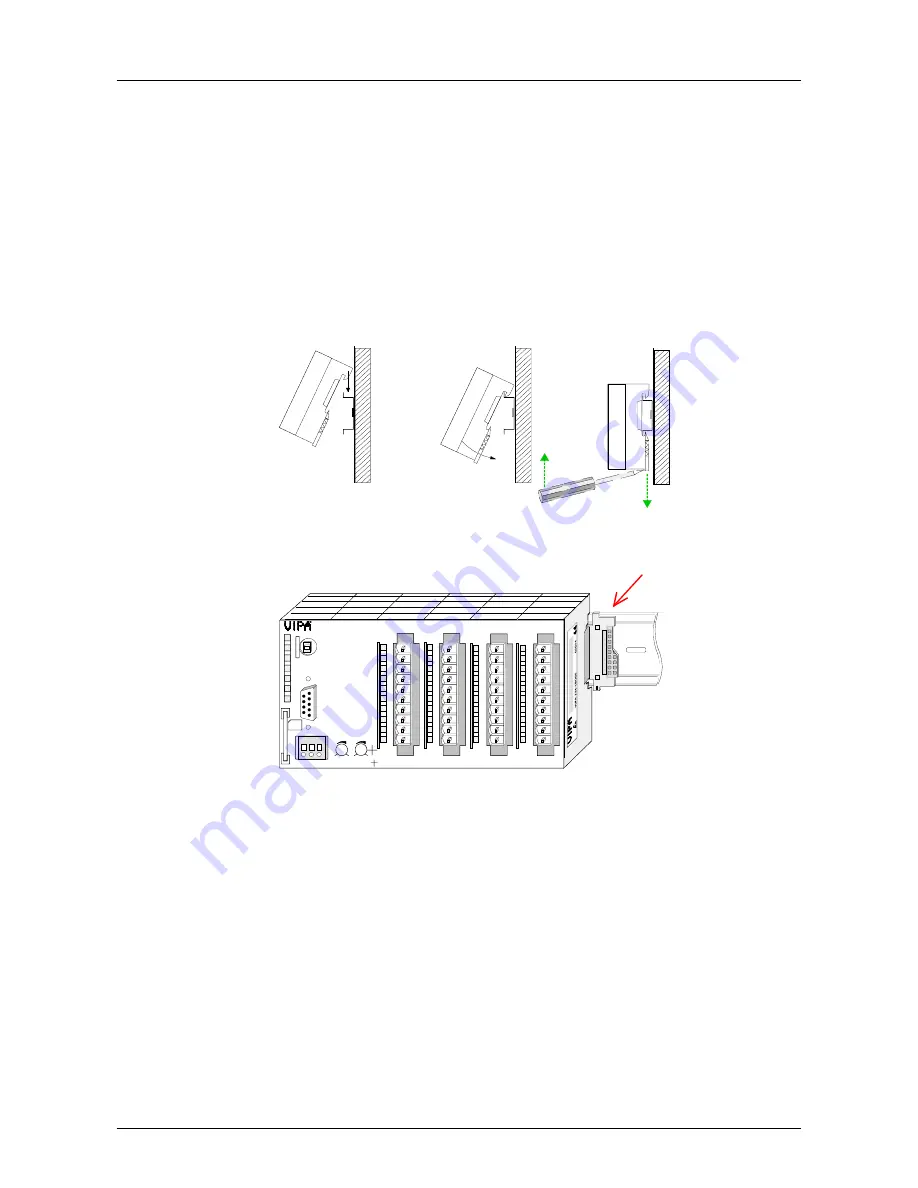
The installation of a System 100V module works via snapping on a norm
profile head rail.
Ç
Ç
Dismantling
When using expansion modules, you have to clip the included 1tier bus
connector at the right side to the module from behind before the
installation.
VIPA 115-6BL02
CPU 115
P1
P2
X1
DC24V
MMC
M
P
I
2
0
0
PW
SF
FC
MC
L+ M PE
X 2
3 4
R
S
RUN
STOP
MRST
DI 8xDC24V
.0
.1
.2
.3
.4
.5
.6
.7
1
2
3
4
5
6
7
8
9
I0
DI 8xDC24V
.0
.1
.2
.3
.4
.5
.6
.7
1
2
3
4
5
6
7
8
9
I0
DO 8xDC24V
L+
.0
.1
.2
.3
.4
.5
.6
.7
F
1
2
3
4
5
6
7
8
9
I0
DO 8xDC24V
L+
.0
.1
.2
.3
.4
.5
.6
.7
F
1
2
3
4
5
6
7
8
9
I0
X3
X4
X5
X6
A B
DI 16(20)xDC24V
DI 16(20)xDC24V, 0,5A
•
Plug in via CageClamps, core cross-section 0.08...2.5mm
2
•
Total isolation of the cables during module changes
•
EMV resistance ESD/Burst acc. IEC 61000-4-2 / IEC 61000-4-4
(to level 3)
•
Shock resistance acc. IEC 60068-2-6 / IEC 60068-2-27 (1G/12G)
•
Operating temperature: 0... + 60°C
•
Storage temperature: -25... + 70°C
•
Relative humidity: 5 ... 95% without condensation
•
fan-less operation
Structure and
dimensions
Installation
Operation security
Environmental
conditions


