Printer Maintenance
49
Replace Cutter Assembly
If replacing the cutter assembly, continue with the following steps.
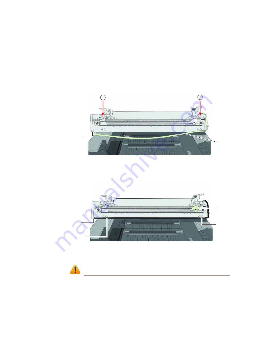
1. Use a small flat-head screwdriver to release the wire harness connector for the
cutter assembly (labeled CUTTER MODULE) and separate it (
2. Remove the two screws (a) securing the cutter assembly and remove the
assembly (
).
Figure 10
Cutter assembly on clamshell
3. Line up the mounting holes and guides on the new cutter assembly and the front
of the clamshell. Insert and tighten the screws to secure the assembly.
4. Make sure the cutter is at the side of the cutter assembly.
5. Reattach the wire harness connector (labeled
CUTTER MODULE
) for the cutter
assembly at the side of the clamshell (
Be sure to reattach the correct connector for the cutter assembly.
6. Gently pull the black cable out of the notches at the bottom corners of the cutter
assembly so that the output module can be installed.
notch
cable
a
a
cutter
guide
guide
notch
for cable
Summary of Contents for VP6 Series
Page 1: ...U s e r G u i d e VIPColor VP6xx Printer Series ...
Page 36: ...36 Using the Printer ...
Page 58: ...58 Printer Maintenance ...


