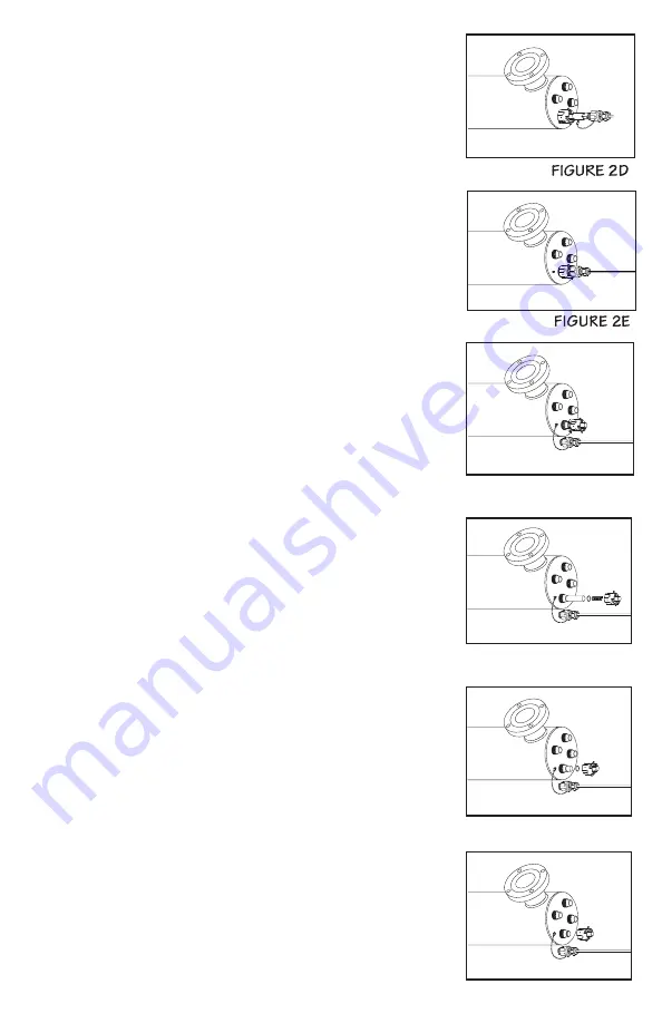
is fully seated onto the UV lamp (Figure 2D).
4. Once the lamp is fully seated on the connector, slide the
connector up to the retaining nut. Once the connector is
located fully against the retaining nut, slide the metal ring back
in to lock the connector in place (Figure 2E). As this connector
is keyed to the reactor chamber, make sure the notch on the
connector (Figure 2D) is located over the ground lug located on
the reactor chamber.
Quartz Sleeve Replacement / Cleaning:
Mineral deposits and sediment may accumulate on the quartz sleeves
decreasing the UV energy detected. Good maintenance of filtration
equipment will reduce the accumulation of residues. If necessary,
remove the quartz sleeves and clean with a commercially available
scale remover (CLR, Lime-Away, etc.) and a lint free cloth. Repeat
the process as often as necessary to keep the quartz sleeves clean.
Be sure to remove all traces of cleaning fluid from the sleeve before
it is reinstalled in the reactor (be sure not to allow liquid inside the
sleeves).
1. Shut off the upstream water supply that feeds water into the
reactor chamber.
2. Open a downstream faucet to release any pressure that may be
built-up in the system.
3. Remove the UV lamps by following steps 1 & 2 as outlined in the
“Lamp Replacement” section on page
8.
4. Remove the retaining nuts by turning counter clockwise (Figure
3a). Drain chamber through drain port. Grasp the quartz sleeve
and fully remove from the reactor chamber. Remove both o-rings.
As with the lamp, make sure the sleeves are removed from the
reactor chamber being careful not to angle the sleeve as they are
removed from the reactor (Figure 3b) to avoid breakage. Make sure
not to let the sleeve fall inside the chamber after the sleeve end
passes the threaded port.
5. Clean the sleeve as outlined in above, or replace with a new
sleeve. Reinstall the quartz sleeve in the reverse order. To install
the sleeves, carefully insert the sleeves into the reactor chamber
(do not drop) and push the sleeves (Figure 3c), to the opposite
end of the chamber making sure the sleeves are inserted into the
corresponding holes on the opposite end of the chamber. Install a
wetted o-ring (Part number 410867) onto both ends of the sleeves
until they are positioned against the chamfered seat (Figure 3d).
6. Reinstall the retaining nut on the reactor chamber and tighten by
turning clockwise. The retaining nuts should be hand- tightened
only, the use of a wrench is not required, nor recommended.
Reinstall the connector as outlined in step four of the “Lamp
Replacement” section.
7. Slowly turn on water and pressurize the reactor to verify that there
are no leaks.
8. Reconnect to power source and follow the Controller start-up
sequence to make sure the system is operating properly.
FIGURE 3A
FIGURE 3B
FIGURE 3C
9
FIGURE 3D


