background image

UV Sensor Replacement / Cleaning (SHFM models only):

The UV sensor is a very delicate instrument. Extreme care is 
required when handling and cleaning. The sensor window itself 
is constructed from quartz which is extremely fragile, be careful 
you do not chip or break this quartz window. Manufacturer’s 
warranty does not cover damage due to neglect or misuse.

Mineral deposits and sediment may accumulate on the sensor window decreasing 

the UV energy detected. Good maintenance of pre-treatment equipment will 

reduce the accumulation of residues. If the system indicates that the UV intensity 

is low, one cause may be a stained quartz sleeve and/or sensor window. To clean 

follow steps 1-3 below.

1.   Before removing the sensor assembly, follow the steps as outlined in the “Quartz  

Sleeve Replacement And/Or Cleaning” section. The quartz sleeves should be 

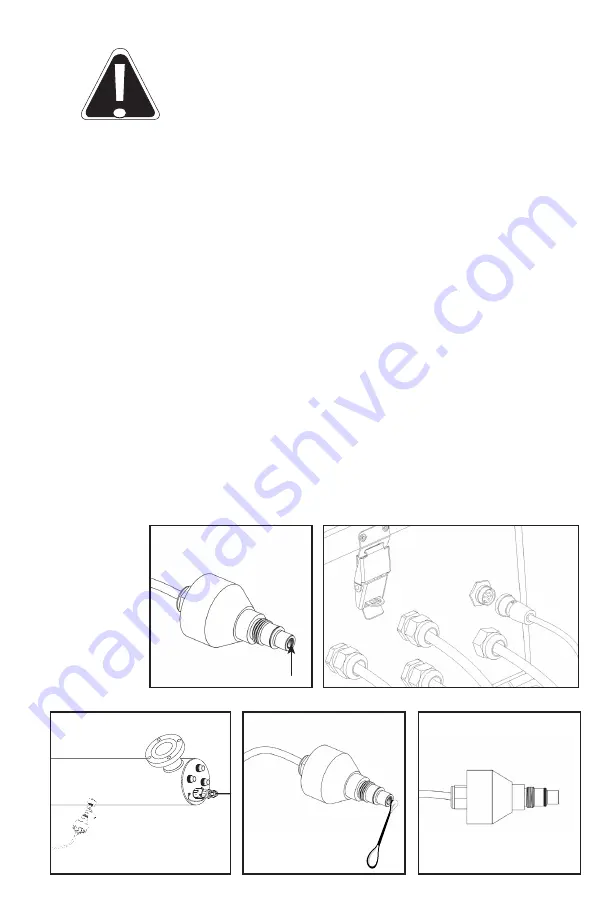
cleaned at the same time as the UV sensor. Disconnect the UV sensor from the 

Hi-Flo Monitored (BA-ICE-M-HF) controller by disconnecting the sensor cable, 

turning the collar counter-clockwise (Figure 4B). To remove the sensor, grasp the 

body of the sensor and rotate counter-clockwise (Figure 4C) until the sensor is free 

of the threaded sensor port.

2.   Once the sensor is free from the reactor chamber, soak in a commercial scale 

remover (CLR or Lime-A-Way) for 30 minutes and clean the quartz window (Figure 

4A) with a lint free cotton swab (Figure 4D). Follow all manufacturer’s instructions 

regarding the cleaning fluid used. Do not use an abrasive cleaner on the sensor 

window. Scratching of the sensor window will void any manufacturer’s warranty 

on this item.

3.   Ensure sensor lens is rinsed free of cleaning solution. Carefully reassemble the 

sensor assembly with o-ring (Figure 4E) into the sensor boss. Screw the sensor 

into the boss and tighten to achieve a water-tight seal. DO NOT OVER TIGHTEN. 

Attach the sensor cable to the Controller and return to service (Figure 4B).

FIGURE 4A

FIGURE 4B

FIGURE 4C

FIGURE 4D

FIGURE 4E

10

Summary of Contents for SHF-140

Page 1: ...FM 140 SHFM 140 2 SHF 180 SHF 180 2 SHFM 180 SHFM 180 2 425 Clair Rd W Guelph Ontario Canada N1L 1R1 t 1 519 763 1032 tf 1 800 265 7246 US and Canada only t 31 73 747 0144 Europe only f 1 519 763 5069...

Page 2: ...fe coated for stability longer life and increased efficiency Even lamps that look the same will not perform the same Get water confidence with genuine lamps proven to disinfect over their entire lifet...

Page 3: ...ou have taken the first step in ensuring the safety of your water supply by using a totally non intrusive physical disinfection method Your Sterilight system uses the most advanced UV technology on th...

Page 4: ...ce on UV Chamber unless UV chamber has been isolated and depressurized Never service UV Lamps Sleeves or associated hardware until depressurization of UV chamber has been confirmed Hot chamber Allow U...

Page 5: ...gile Eye Protection WEEE waste electrical or electronic equipment This symbol indicates that you should not discard wasted electrical or electronic equipment WEEE in the trash For proper disposal cont...

Page 6: ...d separately 260192 R NORTH AMERICAN NEMA 5 15P 3 PRONG GROUNDED 260198 R CONTINENTAL EUROPEAN CEE 7 7 2 PIN WITH GROUND SCHUKO 260193 R NO CONNECTOR 3 WIRE BARE LEADS 214 fused quartz sleeves with fi...

Page 7: ...is system should only be connected to a properly grounded grounding type power supply receptacle that is protected by a Ground Fault Circuit Interrupter GFCI Inspect operation of GFCI as per manufactu...

Page 8: ...accept the plug from this system Use only extension cords that are intended for outdoor use Use only extension cords having an electrical rating not less than the rating of the system A cord rated for...

Page 9: ...e must be connected to a grounded receptacle and the lamp connector ground wire connected to the stainless steel reactor chamber The disinfection system is designed to be mounted horizontally within t...

Page 10: ...returned to service Please refer to the complete disinfection procedure as outlined on page 7 of this document If the water is to be consumed while the system is off line the water must be boiled for...

Page 11: ...provided Figure 1E 5 Install the UV lamps and UV sensor as outlined on pages 8 10 6 When all plumbing connections are made slowly turn on the water supply and check for leaks The most likely cause fo...

Page 12: ...it is strongly recommended that the entire distribution system located after the UV be chemically disinfected to ensure that the pipework is free from any bacteriological contaminants The disinfectio...

Page 13: ...om the connector simply slide the two apart Avoid touching the lamp on the glass portion Handling the lamp at the ceramic ends is acceptable however if you must touch the lamp glass please use gloves...

Page 14: ...e retaining nuts by turning counter clockwise Figure 3a Drain chamber through drain port Grasp the quartz sleeve and fully remove from the reactor chamber Remove both o rings As with the lamp make sur...

Page 15: ...sensor Disconnect the UV sensor from the Hi Flo Monitored BA ICE M HF controller by disconnecting the sensor cable turning the collar counter clockwise Figure 4B To remove the sensor grasp the body of...

Page 16: ...ired lamp from the reactor chamber dispose of in accordance with local or regional laws and regulations 3 install new UV lamp and connect it to lamp connector refer to page 8 4 replace lamp connector...

Page 17: ...quired to Indicates the UV level is nearing the point of unsafe UV intensity UV system should be immediately serviced Indicates the UV level has now reached a level that is unsafe At this level the wa...

Page 18: ...sh button SWITCH two times in succession and follow steps as outline on page 11 regarding the operation of this feature 4 Lamp failure blank screen Please refer to page 10 for explanation of this feat...

Page 19: ...This Y cable comes with 20 meters 65 of cable for the 4 20 mA signal To install first remove the existing sensor cable from the HF Enclosure Figure 5B and affix the new Y cable Figure 5C Next attach...

Page 20: ...quent use of water run water until it returns to ambient temperature install temperature management valve Water Appears Milky Caused by air in the water lines run water until air is purged Unit Leakin...

Page 21: ...quartz sleeves and sensor eye LED flashing A2 and then back to UV level low UV alarm deferral has been activated UV level has dropped below 50 and the audible alarm has been muted by pressing the res...

Page 22: ...68 lbs 31 8 kg 70 lbs 35 5 kg 78 lbs 36 4 kg 80 lbs Electrical Voltage 100 240V 50 60Hz 100 240V 50 60Hz 100 240V 50 60Hz 100 240V 50 60Hz Power Consumption 350 W 350 W 440 W 440 W Lamp Watts 300 W 30...

Page 23: ...t the problem and identify a solution Please have available the model number system type the date of purchase the name of the dealer from whom you purchased your Sterilight product the source dealer a...

Page 24: ...under these warranties will be covered under warranty up to the end of the warranty period applicable to the original part The above warranties do not include the cost of shipping and handling of retu...

Reviews: