background image

Basic Systems incorporating BA-ICE-HF controller:

 Operation:

11


1. Lamp life remaining (days):

Each controller tracks the number of days of operation of the lamp and the controller. The 

default screen will display the total lamp life remaining (in days). The controller will count 

down the number of days remaining until the lamp requires changing (365 days to 1 day). 

At “0” days, the controller will display             on the display and supply an intermittent 

audible chirp (1 second on, 5 seconds off), indicating the need to change the lamp.

DEFERRAL

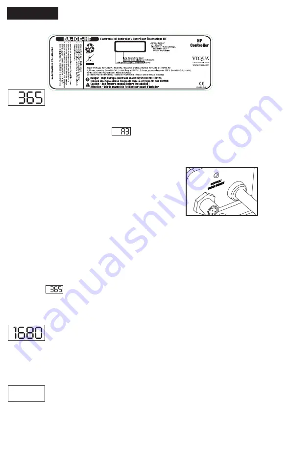
 - Once the “A3” or end of lamp life message is shown on the LED screen, 

the audible alarm can be deferred up to 4 separate times. The delay switch is designed 

to allow you time to address the alarm while you obtain a new UV lamp. This can be 

done by simply depressing the push-button “RESET” switch, 

which is located on the left side of the controller. Each time the 

reset switch is pressed the controller alarm is deferred seven 

days. Once the final 7 day deferral has been reached the alarm 

can only be silenced by changing the UV lamp and manually 

resetting the controller timer. To do this please follow the step 

by step instructions below: 

RESETTING LAMP LIFE:

1. disconnect power supply from controller

2.  remove expired lamp from the reactor chamber (dispose of in accordance with local or 

regional laws and regulations.)

3. install new UV lamp and connect it to lamp connector (refer to page


8

)

4.  replace lamp connector

5.  hold down the “RESET” switch while reapplying power to the controller until you see 

“rSEt”, then release

6.  5 second delay will occur until you hear an audible tone & LED display will read  

once again 

Once you hear the tone, let go of the switch and the counter will be reset. Even though 

the alarm on the system can be deferred for a period of time, it is important to address 

each and every alarm condition as they are indicating that there is a potential problem with 

the system and should be remedied.


2. Total days of operation:

The controller also displays the total running time of the controller. To obtain this reading, 

press the push-button SWITCH once. The total running time of the controller will be 

numerically displayed in days. This information will remain displayed for ten seconds and 

will then revert back to the lamp life remaining default screen. It should be noted that this 

value cannot be reset. 


3. Lamp failure (blank screen):

When the system recognizes LAMP FAILURE (no current running through the lamp), 

the 4-segment display will be blank (no default LAMP LIFE REMAINING screen) and the 

system will supply an intermittent audible tone (1 second on, 1 second off). The system 

will remain in this state, until this condition is remedied.

Summary of Contents for SHF-140

Page 1: ...FM 140 SHFM 140 2 SHF 180 SHF 180 2 SHFM 180 SHFM 180 2 425 Clair Rd W Guelph Ontario Canada N1L 1R1 t 1 519 763 1032 tf 1 800 265 7246 US and Canada only t 31 73 747 0144 Europe only f 1 519 763 5069...

Page 2: ...fe coated for stability longer life and increased efficiency Even lamps that look the same will not perform the same Get water confidence with genuine lamps proven to disinfect over their entire lifet...

Page 3: ...ou have taken the first step in ensuring the safety of your water supply by using a totally non intrusive physical disinfection method Your Sterilight system uses the most advanced UV technology on th...

Page 4: ...ce on UV Chamber unless UV chamber has been isolated and depressurized Never service UV Lamps Sleeves or associated hardware until depressurization of UV chamber has been confirmed Hot chamber Allow U...

Page 5: ...gile Eye Protection WEEE waste electrical or electronic equipment This symbol indicates that you should not discard wasted electrical or electronic equipment WEEE in the trash For proper disposal cont...

Page 6: ...d separately 260192 R NORTH AMERICAN NEMA 5 15P 3 PRONG GROUNDED 260198 R CONTINENTAL EUROPEAN CEE 7 7 2 PIN WITH GROUND SCHUKO 260193 R NO CONNECTOR 3 WIRE BARE LEADS 214 fused quartz sleeves with fi...

Page 7: ...is system should only be connected to a properly grounded grounding type power supply receptacle that is protected by a Ground Fault Circuit Interrupter GFCI Inspect operation of GFCI as per manufactu...

Page 8: ...accept the plug from this system Use only extension cords that are intended for outdoor use Use only extension cords having an electrical rating not less than the rating of the system A cord rated for...

Page 9: ...e must be connected to a grounded receptacle and the lamp connector ground wire connected to the stainless steel reactor chamber The disinfection system is designed to be mounted horizontally within t...

Page 10: ...returned to service Please refer to the complete disinfection procedure as outlined on page 7 of this document If the water is to be consumed while the system is off line the water must be boiled for...

Page 11: ...provided Figure 1E 5 Install the UV lamps and UV sensor as outlined on pages 8 10 6 When all plumbing connections are made slowly turn on the water supply and check for leaks The most likely cause fo...

Page 12: ...it is strongly recommended that the entire distribution system located after the UV be chemically disinfected to ensure that the pipework is free from any bacteriological contaminants The disinfectio...

Page 13: ...om the connector simply slide the two apart Avoid touching the lamp on the glass portion Handling the lamp at the ceramic ends is acceptable however if you must touch the lamp glass please use gloves...

Page 14: ...e retaining nuts by turning counter clockwise Figure 3a Drain chamber through drain port Grasp the quartz sleeve and fully remove from the reactor chamber Remove both o rings As with the lamp make sur...

Page 15: ...sensor Disconnect the UV sensor from the Hi Flo Monitored BA ICE M HF controller by disconnecting the sensor cable turning the collar counter clockwise Figure 4B To remove the sensor grasp the body of...

Page 16: ...ired lamp from the reactor chamber dispose of in accordance with local or regional laws and regulations 3 install new UV lamp and connect it to lamp connector refer to page 8 4 replace lamp connector...

Page 17: ...quired to Indicates the UV level is nearing the point of unsafe UV intensity UV system should be immediately serviced Indicates the UV level has now reached a level that is unsafe At this level the wa...

Page 18: ...sh button SWITCH two times in succession and follow steps as outline on page 11 regarding the operation of this feature 4 Lamp failure blank screen Please refer to page 10 for explanation of this feat...

Page 19: ...This Y cable comes with 20 meters 65 of cable for the 4 20 mA signal To install first remove the existing sensor cable from the HF Enclosure Figure 5B and affix the new Y cable Figure 5C Next attach...

Page 20: ...quent use of water run water until it returns to ambient temperature install temperature management valve Water Appears Milky Caused by air in the water lines run water until air is purged Unit Leakin...

Page 21: ...quartz sleeves and sensor eye LED flashing A2 and then back to UV level low UV alarm deferral has been activated UV level has dropped below 50 and the audible alarm has been muted by pressing the res...

Page 22: ...68 lbs 31 8 kg 70 lbs 35 5 kg 78 lbs 36 4 kg 80 lbs Electrical Voltage 100 240V 50 60Hz 100 240V 50 60Hz 100 240V 50 60Hz 100 240V 50 60Hz Power Consumption 350 W 350 W 440 W 440 W Lamp Watts 300 W 30...

Page 23: ...t the problem and identify a solution Please have available the model number system type the date of purchase the name of the dealer from whom you purchased your Sterilight product the source dealer a...

Page 24: ...under these warranties will be covered under warranty up to the end of the warranty period applicable to the original part The above warranties do not include the cost of shipping and handling of retu...

Reviews:

Related manuals for SHF-140