background image

2

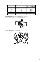
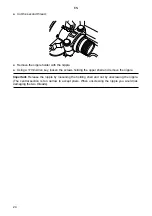
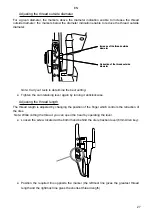
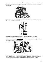
 Position  the  setting  cam  according  to  the  tube  diameter  and  the  desired  outside  thread 

diameter (see pages 26 and 27).
Tighten the lever again by turning it in the direction indicated by the arrow.

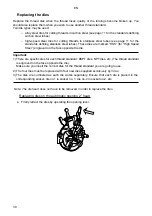
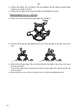
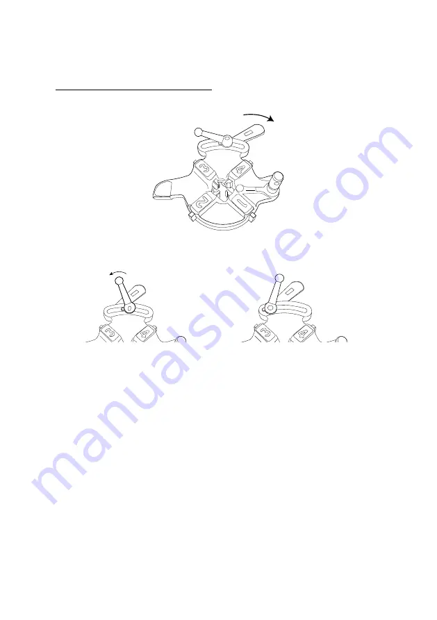
Replacing dies for the 1/4 – /8” head

Retract the dies by tilting the die bearer plate lever clockwise:


 Unscrew  the  die  bearer  plate  tightening  lever  and  move  the  plate  to  the  left  as  far  as  the 

stop:


 Remove the anti-stop finger from its socket and move the plate to the left up to the stop, 

which frees the dies.

The anti-stop finger of the washer prevents the die bearer plate from moving into the “die 

freeing” position:

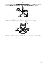
Remove the dies, in any order. (To remove die no.3, lift the die bearer plate lever).

EN 

Summary of Contents for 162120

Page 1: ...Threading machine for tubes up to 2 Instruction Manual 162120 EN ...

Page 2: ...C relating to electrical equipment designed for use within certain voltage limits Low voltage 2004 108 EC ElectroMagnetic Compatibility relating to electromagnetic compatibility and repealing Directive 89 336 EEC 98 37 EC relating to machinery and to relevant national legislation transposing these directives Complies with harmonized European standards EN 55014 1 EN 55022 Epernay August 24th 2009 E...

Page 3: ...EN ...

Page 4: ... for the Sanitary Environmental engineering and Roofing trades supplies the tools you use in your everyday work Virax showing off your talent This documentation has been produced with care to enable you to use the machine to its best and in complete safety We strongly recommend you to read this instruction manual carefully before using the machine and to keep it within easy reach of the machine EN...

Page 5: ...ns 11 Diameters of tubes which can be threaded 11 Tubes which can be threaded cut or reamed 11 Available thread types 12 Setting the length and outside diameter of the thread 12 Option of installing a groover 12 General characteristics 13 Moving and setting up the machine 14 Moving by lifting equipment 14 Moving manually 15 Moving using a trolley 15 Slope of the machine 17 Positioning a tube 18 Po...

Page 6: ...tube cutter 37 Replacing the reaming cone 38 Replacing the reamer 38 Replacing the front chuck jaws 39 Replacing the front chuck jaw holders 41 Diagnostics and fault fixes 44 Machine operating problems 44 Thread cutting problems 45 Tube cutting problems 47 Reaming problems 47 Exploded views 48 Exploded view of the frame 48 Exploded view of the motor and the oil pump 49 Exploded view of the transmi...

Page 7: ...eeded to ensure that the tool is in perfect working order All safety devices switches or other damaged or defective parts must be appropriately repaired or replaced by a qualified technician Warning Be sure to use the tool and its accessories in accordance with the safety instructions Consider the range of options for the tool taking into account the working conditions and the task to be carried o...

Page 8: ...ne of your colleagues Moreover when loosening if the joint has not been released you will subject the motor to a force which may damage it The machine is not a winch You may be tempted to use the force of the motor to raise or lower loads This use is prohibited as the machine could topple over and jettison its load Moreover you may damage the motor The machine is not intended for coating the threa...

Page 9: ...st have a grounding pin connected to a ground connection in the workshop Do not pull the machine by its power cable This is not a rope Likewise do not disconnect the machine by pulling on the cable Instructions relating to your protection and the protection of those around you It is essential to place the tube on one or more pipe holders also called benches Virax part numbers pipe holder without f...

Page 10: ...urself on contact with sharp items in particular cutter wheel thread dies reaming cone internal edges of the tube Wear gloves for handling metal turnings these can cause bad fine and deep cuts Wear gloves if you are allergic to lubrication oil Pay attention to crushing hazards in particular when lowering the tube cutter the die head or the reamer and when the saddle is moving Wait for the motor to...

Page 11: ...e Identify as much as possible any cracks overlarge play etc and in general any anomaly Regularly change the four dies of the die head especially when the turnings become less whole and more broken up Regularly check the oil level You must not thread your tubes without a sufficient oil flow You must use one of the oils supplied by Virax as all mechanical tests have been carried out using these oil...

Page 12: ...perations must only be carried out by personnel approved by Virax Important Virax may not be held liable for accidents which occur as a result of an unauthorized maintenance operation Storage instructions Store the machine powered off in a dry place where there is no risk of water or dust spatter and cover it with a tarpaulin EN ...

Page 13: ...pressure Technical delivery conditions Part 5 Stainless steel tubes EN 10217 7 August 2005 Welded steel tubes operating under pressure Technical delivery conditions Part 7 Stainless steel tubes 2 Carbon steel tubes EN 10208 2 October 1996 Steel tubes for carrying combustible fluids Technical delivery conditions Part 2 Tubes of specification class B EN 10216 1 December 2002 Seamless steel tubes ope...

Page 14: ... fitted with a BSPT NPT scale as standard Setting the length and outside diameter of the thread The heads allow the length and outside diameter of the thread to be set Option of installing a groover In addition to the three basic functions cutting reaming threading the machine can be used with a Virax groover part no 162400 available as an option for hollow tubes in carbon steel with diameters fro...

Page 15: ... kg Overall dimensions of the machine on its feet length x width x height in mm 1170 x 705 x 1100 Acoustic power level LwA 92 dB A Acoustic pressure at the user s ears LwA 84 dB A LpMaxPeak 130 db C Machine supplied with 4 feet 1 x 5L drum of cutting oil for steel tubes 1 x 2 automatic die head 1 set of dies 1 2 3 4 1 set of dies 1 2 1 set of 2 carbon brushes 1 spare cutter wheel EN ...

Page 16: ...ling the various heads Warning Do not forget to do this as the die head is simply fixed to its shaft and can therefore fall off during transport Use a 2 tube of sufficient length to overlap the two sides of the machine by about 30 cm Carefully ream each tube end to avoid the tube edges cutting the lifting cable see page 20 for the reaming procedure Insert the tube into the machine and check that t...

Page 17: ...eded to raise the machine Raise and move the machine only by using its handles The other parts of the machine do not give a secure grip Moving using a trolley The folding trolley designed by Virax part no 162460 enables the 2 machine to be transported and used without setting it back on its feet EN ...

Page 18: ...e machine Lower the trolley handle fold up the trolley completely lock the retaining hook Warning don t forget to do this and transport the trolley holding it by its handle Place the front wheels on the edge of the lorry and raise the rear section of the trolley so as to be able to load it fully into the lorry Warning 1 Secure the machine firmly to its trolley using the screws supplied whether the...

Page 19: ... its feet or on its trolley slopes 2 to the front 2 This slope prevents oil flowing towards the back in the tube Check therefore that this slope is maintained where work is to be carried out Be careful to secure the feet firmly to avoid the machine falling EN ...

Page 20: ...The front chuck is a hammer chuck strike several blows towards you when you are on the operator s side to tighten the jaws onto the tube To loosen the chuck give successive blows in the opposite direction Positioning short tubes Place the tube in the front chuck and tighten the chuck just so it holds the tube Lower the die head and move the saddle so that the dies come into contact with the tube e...

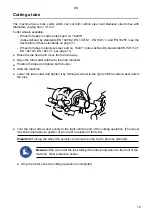
Page 21: ...e head and move the reamer away Open the tube cutter relative to the tube diameter Position the tube and tighten both chucks Start the machine Lower the tube cutter and tighten it by turning its wheel to the right until the cutter wheel enters the tube Turn the tube cutter wheel evenly to the right until the end of the cutting operation The wheel must be turned about a quarter of a turn per revolu...

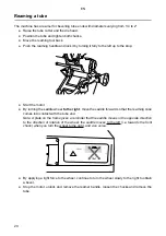
Page 22: ...l to the right move the saddle forward so that the reaming cone comes into contact with the tube end Note A plate on the frame gives a reminder that the saddle moves in the opposite direction to the direction of rotation of the wheel the saddle moves to the left i e towards the front chuck when you turn the wheel to the right and vice versa By applying a light force to the wheel continue to turn t...

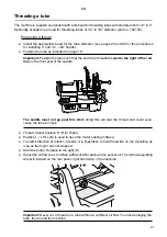
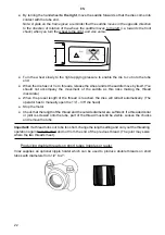
Page 23: ... front post of the saddle The saddle must not go past this limit doing this will tear the thread and could even cause the tube to crack Thread Select position R R for Right Position L L for Left is used to have the motor rotating leftwise To switch direction of rotation à l autre it is imperative to hold the switch on the 0 position as long as the motor has not stopped Start the motor Rotation to ...

Page 24: ...ks making the thread inaccurate When the preset length of the thread is reached the dies will retract automatically The operator has to manually open the 1 4 3 8 die head Stop the motor Check that the length of the thread and the outside diameter are sufficient if a threaded collar or joint is screwed onto the tube part of the thread must still be visible Loosen the chucks and remove the tube Impo...

Page 25: ...h mm Virax part numbers 1 2 46 162450 3 4 53 162451 1 56 162452 1 66 162453 1 66 162454 2 73 162455 Produce the first thread as indicated in the previous paragraph Screw the threaded section fully onto the nipple holder Clamp the nipple holder in the front chuck EN ...

Page 26: ...en key loosen the screws holding the upper shell and remove the nipple Important Release the nipple by loosening the holding shell and not by unscrewing the nipple The central section is too narrow to accept pliers When unscrewing the nipple you would risk damaging the two threads EN ...

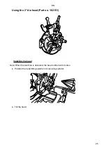
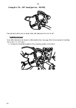
Page 27: ...5 Using the 2 die head Part no 162151 Installing the head Note When the machine is delivered the head is fitted with its dies Position the head tilting spindle in its receiving cylinder Tilt the head EN ...

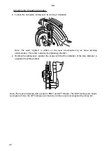
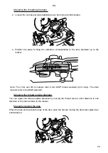
Page 28: ...ing anticlockwise This arrow indicates the tightening direction Holding the setting lever position the scale such that the indication of the tube diameter is opposite the setting marker Note The head is delivered with a scale for BSPT and NPT threads The BSPT settings are shown by single red lines the NPT settings are shown by red lines each accompanied by a blue dot EN ...

Page 29: ...thread length is adjusted by changing the position of the finger which controls the retraction of the dies Note While cutting the thread you can open the head by operating the lever Loosen the screw located at the bottom and behind the die retraction lever 6mm Allen key Position the required line opposite the marker the leftmost line gives the greatest thread length and the rightmost line gives th...

Page 30: ...to thread tubes with diameters from 1 4 to 3 8 Installing the head Note When delivered the head is not fitted with its dies See page 32 for the procedure for installing dies for the 1 4 3 8 head Position the head tilting spindle in the receiving cylinder on the frame EN ...

Page 31: ...d 3 8 G markers refer to the BSPT thread standard G for Gas The other markers refer to the BSW standard Adjusting the thread outside diameter You can adjust the thread outside diameter by moving the thread scale a short distance in one direction or the other relative to the marker Manually opening the dies When the tube end reaches the tips of the dies open the dies by moving the die bearer plate ...

Page 32: ...l engraved on the face opposite the die Important 1 There are specific dies for each thread standard BSPT dies NPT dies etc The thread standard is engraved on the face opposite the die Make sure you insert the correct dies for the thread standard you are going to use 2 The four dies must be replaced with four new dies supplied exclusively by Virax 3 The dies are numbered as each die works separate...

Page 33: ... to retain the initial setting of the head Remove the worn dies and loosen the plate slightly Put the new dies in place notch to the rear in compliance with the numbering die no 1 in socket no 1 die no 2 in socket no 2 etc Insert each die until you can feel that the die is blocked by the ball inside the socket Note The line engraved on the die is used to position the die when it is placed in a man...

Page 34: ...ies by tilting the die bearer plate lever clockwise Unscrew the die bearer plate tightening lever and move the plate to the left as far as the stop Remove the anti stop finger from its socket and move the plate to the left up to the stop which frees the dies The anti stop finger of the washer prevents the die bearer plate from moving into the die freeing position Remove the dies in any order To re...

Page 35: ... notch turned anticlockwise Insert each die up to its stop Note The dies may be inserted in any order Move the die bearer plate lever to the right which places the cams in the dies Position the die bearer plate according to the tube diameter and the desired external thread diameter see page 29 tighten up the lever EN ...

Page 36: ...ersonnel approved by Virax Cleaning the oil system Remove turnings which have accumulated in the receiving bin and clean the scrap receiver Warning Wear gloves when handling turnings risk of being badly cut Remove the scrap receiver and the oil filter grid and clean the strainer Note The strainer can also be removed to facilitate cleaning EN ...

Page 37: ... clarity drain it and replace with new oil The drain plug is located on the front of the machine Note Drain the machine also when it is being transported over any significant distance Replacing the motor brushes The motor will stop working if one of its brushes is worn Change both brushes Disconnect the machine Remove the protective grids for both brushes One grid is located on the operator s side...

Page 38: ...e motor shaft Tighten up the rear chuck main shaft blind collar using a 5mm spanner until the play disappears Replacing the cutter wheel The cutter wheel must be replaced if it shows signs of wear or if you need to cut tubes in a different material Two wheels are available depending on the material used for the tube wheel for tubes in carbon steel part no 162470 wheel for tubes in stainless steel ...

Page 39: ...be cutter Replace the tube cutter if it shows signs of cracking of it it is broken Tube cutter for the 162120 part no 753072 Using an 8mm gudgeon punch remove the tube cutter shaft by striking towards the front of the machine Remove the tube cutter and replace it with a new one Replace the tube cutter and insert it using the gudgeon punch by striking towards the front of the machine EN ...

Page 40: ... the cone replace it with a new one and replace the gudgeon Replacing the reamer The reamer must be replaced if it shows cracking signs of it it is broken Complete tool for the 162120 part no 753074 Block the saddle with a wooden block placed between the front chuck and the saddle Remove the gudgeon securing the reamer using an 8mm gudgeon punch Put the new reamer in place and reposition the gudge...

Page 41: ...o replace the jaws Important All three jaws must be replaced at the same time Turn the motor over so as to bring the jaw holder whose jaw is to be removed into vertical position jaw towards the bottom Do not try to turn the chuck by hand Position the chuck groove opposite the jaw holder and insert a 3mm Allen key into the body of the jaw holder Use the key to remove the jaw retaining screw EN ...

Page 42: ...t screw towards the front of the chuck Replace the spring retainer spring and screw and tighten the jaw fastening screw Jaw retaining screw Jaw retaining screw Spring Spring Spring retainer Spring retainer Jaw and jaw transfer set screw shown here on the right of the jaw not visible in the figure Jaw and jaw transfer set screw shown here on the right of the jaw not visible in the figure Jaw transf...

Page 43: ... have to be removed to replace the jaw holders 2 The jaw holders of the centring chuck rear chuck are only subject to slight wear Using a 5mm Allen key unscrew the 6 jaw holding plate screws Dismantle the jaw holding plate crown assembly or ask a colleague to hold the crown by the spindle nose while you remove the jaw holder Spindle nose Spindle nose Crown Crown EN ...

Page 44: ...its three jaw holders over Position the start of the drive ring spiral opposite jaw holder no 1 and insert the jaw holder into the spiral Turn the ring 120 such that the start of the spiral is opposite jaw holder no 2 and insert the jaw holder Do the same for jaw holder no 3 Continue to turn the ring until the jaw holders are completely blocked If necessary replace the chuck crown around the spind...

Page 45: ...43 Screw the jaw holding plate back onto the spindle nose Crown Crown Spindle nose Spindle nose Nose pin Nose pin Slot for spindle nose pin Slot for spindle nose pin EN ...

Page 46: ... ones see page 35 The start button is not working Replace the button Warning do not short circuit the start button see page 8 Attention concerning the machine being restarted after an unexpected stop The motor is burnt out Contact Virax or their representative to change the motor The machine shaft is not driven by the motor The transmission is broken Contact Virax or their representative to change...

Page 47: ... is insufficient The flow is badly regulated Increase the oil flow by turning the flow regulating wheel See page 21 The oil system is fouled Remove turnings from the scrap receiver and the oil filter grid and clean the strainer See page 34 The oil level is insufficient Add oil supplied by Virax see page 9 by pouring it directly into the container Minimum oil level half the diameter of the strainer...

Page 48: ... socket no 1 die no 2 in socket no 2 etc The quality of the thread obtained is not satisfactory Same reasons as above dies fouled or worn or die numbering not complied with See above Oil worn out Drain the oil see page 35 and refill with oil supplied by Virax see page 9 The thread is not deep enough or is too deep The outside diameter of the thread has not been set correctly Adjust the thread diam...

Page 49: ...too hard Replace the tube cutter by a new one See page 37 Use the tube cutter on carbon steel or stainless steel tubes Reaming problems Reaming is not satisfactory The reaming cone is worn Replace the cone by a new one See page 38 The reamer is damaged The reamer is worn or has been used for tubes which are too hard Replace the reamer by a new one See page 38 Use the reamer on carbon steel or stai...

Page 50: ...48 Exploded views If you need a particular part please indicate the title of the exploded view as well as the number of the part on this view Exploded view of the frame EN ...

Page 51: ...49 Exploded view of the motor and the oil pump Pump EN ...

Page 52: ...50 Exploded view of the transmission EN ...

Page 53: ...51 Exploded view of the saddle EN ...

Page 54: ...52 Exploded view of the automatic opening 2 die head EN ...

Page 55: ...53 Exploded view of the 1 4 3 8 die head EN ...

Page 56: ...54 Exploded view of the tube cutter EN ...

Page 57: ...55 Exploded view of the reamer 9 1 26 29 26 11 10 5 26 29 26 4 26 29 8 3 26 7 6 2 26 29 26 12 EN ...

Page 58: ...56 Components of a nipple holder EN ...

Page 59: ...EN ...

Page 60: ...t van onze resellers www virax com EL Συμβουλευτείτε τη λίστα των διανομέων μας στο www virax com PL Listę naszych dystrybutorów znajdziecie na www virax com DE Eine aktuelle Liste unserer Handelspartner finden Sie unter www virax com CS Seznam našich prodejců najdete na www virax com RU Список дилеров вы можете найти на сайте www virax com TR Distribütör lerimizin listesini www virax com web site...

Reviews: