background image


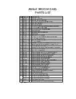
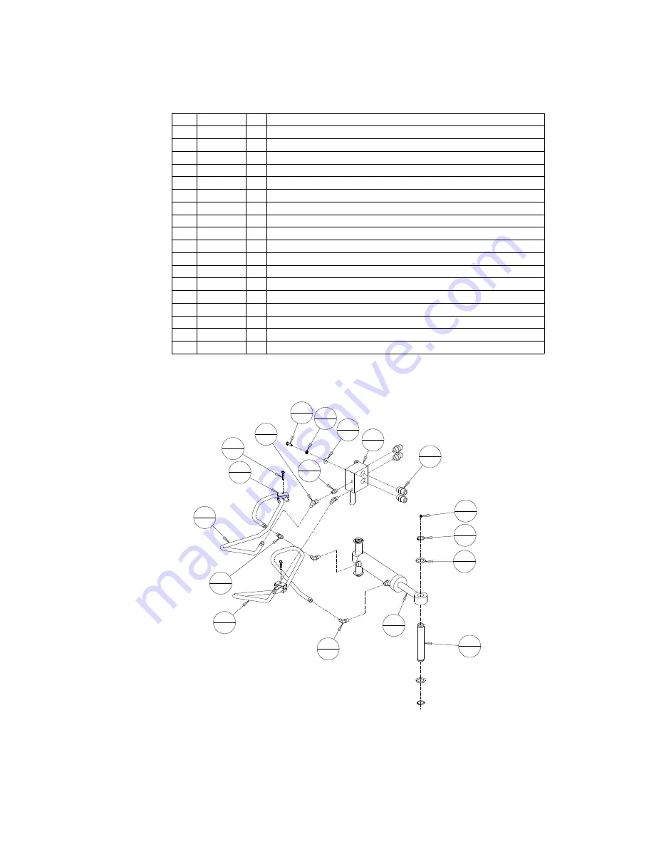
ITEM PART NO. QTY DESCRIPTION

1

1012PP

1

90° FEMALE SWIVEL ELBOW, #6 JIC

2

1034PP

2

1/4"-28 UNF STRAIGHT GREASE FITTING

3

1067PP

2

HOSE CLAMP ASSEMBLY

4

1072PP

1

1/16" DIAMETER IN-LINE RESTRICTOR FITTNG, #6 JIC ENDS

5

1075PP

3

3/8" LOCK WASHER

6

1083PP

3

3/8" FLAT WASHER

7

1094PP

4

1 1/4" DIA X 10 GAGE NARROW RIM MACH BUSHING

8

1095PP

4

1 1/4" DIA HEAVY SNAP RING

9

1117PP

2

5/16" NC X 1 1/2" LG HHCS

10

1125PP

1

HYDRAULIC HOSE, 64" LG, BOTH ENDS #6 JIC FEMALE

11

1127PP

1

HYDRAULIC HOSE, 72" LG, BOTH ENDS #6 JIC FEMALE

12

2137VP

2

CYLINDER PIN

13

6682PP

1

HYDRAULIC CYLINDER

14

6966PP

1

ADAPTER, 6MJ-6MB

15

6997PP

3

90° ELBOW, #6 SAE O-RING MALE TO #6 JIC MALE, SHORT

16

7849PP

3

3/8" NC X 1" LONG HHCS

17

8263PP

4

ADAPTER, 12MJ-12MB

18

8518PP

1

ANGLE BROOM ELECTRO-HYDRAULIC VALVE

2
2

4
1

7
4

8
4

10

1

12

2

13

1

15

3

17

4

18

1

3
2

5
3

6
3

9
2

11

1

16

3

1
1

14

1

OPTIONAL HYDRAULIC ANGLE ASSEMBLY

Summary of Contents for VAB60

Page 1: ...VIRNIG MFG INC Angle Broom OWNERS OPERATORS MANUAL Model Number ___ VAB Serial Number Serial Number less than 81050 Phone 320 393 7080 11 01 09 ...

Page 2: ...ant damage from misuse accidents or negligence nor damage to machine or surrounding environment Claims are limited to replacement parts and a reasonable labor amount This warranty does not cover service mileage downtime or replacement of attachment Upon request for warranty claim an RGA number will be assigned and replacement parts sent prepaid ground freight and invoiced Defective parts need to b...

Page 3: ...h on frame fits onto loader properly Pins must engage through 3 8 plates at bottom of quick tach Slowly roll back attachment Make sure there is no interference between attachment and loader Do not connect this attachment to high flow couplers Make sure hoses do not pinch during roll back Never exceed the maximum attachment operating pressure of 3500 psi After Angle Broom is mounted to the loader l...

Page 4: ...etc that may be injured or damaged by flying debris Always relieve pressure before connecting or disconnecting hydraulic hoses Clean any debris from attachment Pay special attention to any debris in quick tach area The angle broom is designed to be operated so that the brush sweeps debris away from the operator brush spins clockwise when looking from the motor end The brush will spin in the opposi...

Page 5: ...e has the electrical package usually 8 or 14 pin connector for skid loaders connect the electrical plug to the plug on the boom arm of the loader when hooking up the attachment to the loader The angle of the broom should now be controlled by primary electrical switch located in the operator station of the machine If the machine does not have an electrical package there are 2 options to make the Hy...

Page 6: ...rn or missing parts repair or replace as needed Remove any foreign debris such as string wire etc that may have wrapped around the brush head Inspect motor valve hydraulic fittings and hoses for leaks and damage Replace as needed Make sure machine is shut off and hydraulic pressure is relieved before checking for leaks Never use hands to check for high pressure hydraulic leaks The pressure relief ...

Page 7: ...evident Stand core on end with retaining plate still attached and install the new brush sections making sure the drive pins of the wafer engage one of the core drive bars For a snug fit install consecutive wafers so that the drive pins are 180 apart Reinstall the retaining plate and lay core on ground When handling the core do not use the wafers to move the core Lower brush head over core with new...

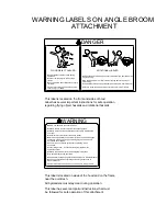
Page 8: ... to follow these instructions could result in injury or death maintaining ALWAYS follow loader safety and operating instructions Check for loose or broken parts before operating repair Failure to follow these instructions could result in injury or death Attachment must be securely latched to loader Stay back 50 feet during operation WARNING NEVER use hands to check for oil leaks Read and understan...

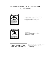
Page 9: ... This label is located on the hood facing the operator This label indicates the Maximum flow rate for this attachment Stay back 50 feet during operation CRUSH HAZARD result in injury or death Failure to follow this instruction could WARNING PINCH POINT Always shut off loader and relieve Failure to follow these instructions could pressure before inspecting or repairing Keep hands clear during opera...

Page 10: ... 1 1 NC HEX NUT TOP LOCK 20 7726PP 1 BRUSH CUTTER HOSE CLAMP ASSEMBLY STANDARD 21 7729PP 1 3 8 NC X 4 1 2 LG HHCS 22 7849PP 12 3 8 NC X 1 LONG HHCS 23 7876VW 1 ANGLE BROOM QUICK TACH FRAME WELDMENT 24 7883VW 1 ANGLE BROOM FOLLOWER LINK WELDMENT 25 7886VW 1 ANGLE BROOM DRIVER LINK WELDMENT 26 7890VW 1 ANGLE BROOM KNUCKLE WELDMENT 27 1 ANGLE BROOM HOOD WELDMENT 28 7906VA 1 ANGLE BROOM HYDRAULIC MOTO...

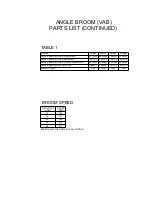
Page 11: ...8572VW 8575VW VAB60 MODEL VAB72 VAB84 VAB96 8589VW 8591VA 8586VW 7895VW 8497VW 8268VW 8500VW 7921VA 8272VA TABLE 1 PARTS LIST CONTINUED ANGLE BROOM VAB RPM SPEED 212 192 173 154 20 22 18 16 8680PP 8680PP 8277PP 8277PP 231 24 GPM FLOW RATE SPEEDS ARE THE SAME FOR ALL WIDTHS BROOM SPEED WEIGHT LBS 970 1035 1095 1160 ...

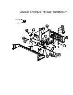
Page 12: ...1 1 ANGLE BROOM LINKAGE ASSEMBLY 3 1 3 2 6 2 7 2 8 8 8 2 36 1 35 1 32 1 26 1 25 1 24 1 23 1 19 1 16 2 14 2 13 2 11 1 10 1 9 4 7 8 6 8 3 4 ...

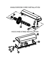
Page 13: ...ANGLE BROOM CORE INSTALLATION HOOD AND STAND INSTALLATION 28 1 1 8 34 8 33 8 31 1 29 1 2 2 4 6 5 6 12 2 22 6 27 1 30 2 41 1 22 6 15 6 ...

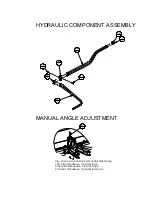
Page 14: ...IN LOCATION FOR VARIOUS DISCHARGE DIRECTIONS LEFT SIDE DISCHARGE PIN LOCATION A RIGHT SIDE DISCHARGE PIN LOCATION D STRAIGHT DISCHARGE PIN LOCATION B OR C A B C D 17 1 18 1 38 2 39 2 40 2 20 1 21 1 15 1 37 1 MANUAL ANGLE ADJUSTMENT ...

Page 15: ...OOM ADAPTER FLANGE WELDMENT 7 7933VP 1 ANGLE BROOM BRUSH RETAINING PLATE 9 1075PP 12 3 8 LOCK WASHER 1 4 2 4 3 6 6 1 8 7 1 6 1 5 1 4 1 3 6 2 4 1 4 MODEL VAB60 ANGLE BROOM CORE WELDMENT 8578VW NUMBER OF WAFERS 30 VAB72 8592VW 36 VAB84 7922VW 42 VAB96 8273VW 48 TABLE 2 SEE TABLE 2 WAFER KIT POLY WIRE COMBO AWC60 AWC72 AWC84 AWC96 ALL STEEL OR POLY WAFERS AVAILABLE PLEASE CONTACT YOUR DEALER 9 6 8 79...

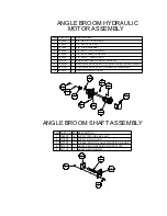
Page 16: ...W 1 BROOM HYDRAULIC MOTOR DRIVE ADAPTER WELDMENT 9 8427VW 1 BROOM HYDRAULIC MOTOR MOUNT WELDMENT 10 8508VP 1 BROOM MOTOR COVER 1 1 2 2 3 1 4 2 7 1 8 1 9 1 10 1 6 4 5 4 ANGLE BROOM HYDRAULIC MOTOR ASSEMBLY ITEM PART NO QTY DESCRIPTION 1 1008PP 4 5 8 NC TOP LOCK HEX NUT 2 7719PP 4 5 8 NC X 2 LG HHCS 3 7773PP 1 2 BEARING WITH 4 HOLE MOUNTING FLANGE 4 7916VP 1 ANGLE BROOM BEARING MOUNT PLATE 5 7917VP ...

Page 17: ...DIA HEAVY SNAP RING 9 1117PP 2 5 16 NC X 1 1 2 LG HHCS 10 1125PP 1 HYDRAULIC HOSE 64 LG BOTH ENDS 6 JIC FEMALE 11 1127PP 1 HYDRAULIC HOSE 72 LG BOTH ENDS 6 JIC FEMALE 12 2137VP 2 CYLINDER PIN 13 6682PP 1 HYDRAULIC CYLINDER 14 6966PP 1 ADAPTER 6MJ 6MB 15 6997PP 3 90 ELBOW 6 SAE O RING MALE TO 6 JIC MALE SHORT 16 7849PP 3 3 8 NC X 1 LONG HHCS 17 8263PP 4 ADAPTER 12MJ 12MB 18 8518PP 1 ANGLE BROOM ELE...

Page 18: ...1 3 4 LYNCH PIN 3 7849PP 3 8 NC X 1 LONG HHCS 4 1 ANGLE BROOM DEFLECTOR WELDMENT 1 2 2 3 4 1 MODEL ABDF60 ANGLE BROOM DEFLECTOR WELDMENT 8582VW HARDWARE QUANTITY 6 WEIGHT LBS 35 ABDF72 8596VW 7 40 ABDF84 8520VW 8 50 ABDF96 8600VW 9 55 OPTIONAL DEFLECTOR SEE TABLE 3 TABLE 3 ...

Page 19: ......

Reviews: