background image


______________ USER’S MANUAL SOLO Airliner RS______________


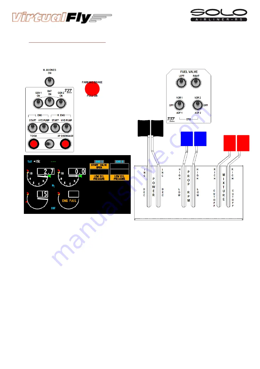
Starting


turbo

fan


(Boeing


737)


engines


In


this


type


of


engine


RPM


and


PROP


MIXTURE


handles


are


not


used,


however,


the


MIXTURE


handle


must


be


outside


the


CUTOFF


area.


1.


Pull


on


the


PARKING


BRAKE


2.


Move


the


POWER


handle


to


DEC


3.


Switch


on


the


BAT


4.


Switch


on


the


L


ENG


“START”

,


the


left


turbine


will


begin


to


rotate


5.


When


the


indicator


N1


reaches


the


2.7


value

,


switch


on


the


FUEL


VALVE


“LEFT”


6.


Once


the


left


engine


is


running


switch


off


the


L


ENG


“START”


7.


Switch


on


the


GEN


1


to


charge


the


batteries.


8.


Switch


on


L


ENG


“HYD


PUMP”


to


activate


the


hydraulic


systems.


9.


Switch


on


M.


AVIONICS


This


procedure


has


started


the


left


engine,


do


the


indications


4,5,6,7,8,9


to


start


the


right


engine.


¡IMPORTANT!


Before


activating


GEN


do


not


forget


to


disable


START,


if


don’t


do


that


the


generator


will


not


charge


the


batteries.


Summary of Contents for SOLO Airliner RS

Page 1: ...______________ USER S MANUAL SOLO Airliner RS______________ User s Manual Rev 1 0 December 2015 ...

Page 2: ...NTS 2 INSTALLATION 3 START UP 4 SELECTION OF PANEL TYPE according to plane 5 ENGINE STARTING 6 SIMULATING THE BOEING 737 7 RADIOSTACK PANEL 8 MULTIPLE SOLO AIRLINER OR MULTIPLE MFS COMPUTER ON THE SAME NETWORK 9 TROUBLESHOOTING 10 WHAT IS NEW ON THIS VERSION 11 REMOTE SESSION 12 TECHNICAL SPECIFICATIONS ...

Page 3: ...ower socket 1 unit 3 Network cable 1 unit 4 3 Magnetic labels Turboprop pack 1 unit 5 4 Magnetic labels Boeing 737 pack 1unit 6 Memory Stick 1unit Content User s manual VFConnect3 exe pluggin FSUIPC and TeamViewer 7 Quick Start Guide 1 unit It is important to save all parts you are not going to use in case you need them in the future 1 2 4 3 5 6 7 ...

Page 4: ...______________ USER S MANUAL SOLO Airliner RS______________ ...

Page 5: ...llow to install your panel Place the panel on the table where it is to be used or on the SOLO support in the latter case follow its instruction manual Connect all the socket power cables from back panel to the multiple power socket 2 Connect the multiple power socket 2 to a 115 230 VAC outlet Connect one end of the network cable 3 to the LAN connector of the Mini computer Connect the other end of ...

Page 6: ...ACTIVATING THE SOLO Press the push button to start the Windows operating system of the mini computer from the SOLO At this time the Windows operating system and all programs found in the SOLO computer will start automatically It is very important that SOLO not be disconnected or Windows stopped while the programs are loading Doing so may cause problems with booting in the future The SOLO is ready ...

Page 7: ...LO you must to execute the file VFConnect3 exe from the MFS P3D desktop computer see chapter 2 If you have the Windows FireWall activated a warning permission to communicate with networks appears you must to click Allow Access Once the connection is established you should see an image like the right At the top This Computer indicates if the software Flight Simulator 2004 X is detected Only Connect...

Page 8: ...ill see one of the following messages Connected Everything is ready you can already begin to fly Searching There is a communication failure between the MFS P3D and the SOLO look at chapter 8 troubleshooting If not get the connection after review chapter 8 please contact the VirtualFly Technical support info virtual fly com In this case the MFS and SOLO are connected In this case the MFS and SOLO a...

Page 9: ...that some aircraft already have their own custom panel as C 172 Mooney B 58 etc but there are customizable panels called GENERIC for other aircraft The planes best suited to the panel are just the planes that MFS P3D incorporates by default Some planes from CARENADO had been tested and that have shown good results Above you can see the panel has 4 types of GENERIC on each of them you can choose th...

Page 10: ...espond to the plane you want to fly in MFS P3D if there isn t a customized label for that plane select a GENERIC label according to the engine type of the plane e g if the plane selected on MFS P3D is Beechcraft King Air A350 you must select the GENERIC TURBO PROP twin engine in the panel If you have chosen a GENERIC panel automatically a new Generic Panel OPTIONS will open were you can select you...

Page 11: ...if the gauges indicators panel selected is for piston turbo prop or turbo fan The panel incorporates some magnetic labels that you must to place in the suitable zone to change the designation of each switch and rotary The default designation of the switches and rotaries without magnetic labels is for piston engines Magnetic Labels pack for turbo prop engines Magnetic labels pack for turbo fan Boei...

Page 12: ...E handle to RICH 3 Move the PROP RPM handle to HIGH 4 Move the POWER handle to DEC 5 Switch on the BAT 6 Switch on the 2 MAGNETO L ENG L and R 7 Push on the red START left push button to start the engine 8 Once the left engine is running switch on the left L ALT to charge the battery 9 Switch on M AVIONICS This procedure has started the single engine if it is a single engine airplane or the left e...

Page 13: ...AL SOLO Airliner RS______________ Stop piston engines 1 Pull on the PARKING BRAKE 2 Move the MIXTURE handle to CUTOFF 3 Switch off the M AVIONICS 4 Switch off the alternator s ALT 5 Switch off the MAGNETO S 6 Switch off the BAT ...

Page 14: ... L ENG START 9 Switch on the GEN 1 to charge the batteries 10 Switch on M AVIONICS This procedure has started the single engine if it is a single engine airplane or the left engine if it is a twin engine plane in the latter case do the indications 6 7 8 9 to start the right engine IMPORTANT Before activating GEN do not forget to disable START if don t do that the generator will not charge the batt...

Page 15: ... the left turbine will begin to rotate 5 When the indicator N1 reaches the 2 7 value switch on the FUEL VALVE LEFT 6 Once the left engine is running switch off the L ENG START 7 Switch on the GEN 1 to charge the batteries 8 Switch on L ENG HYD PUMP to activate the hydraulic systems 9 Switch on M AVIONICS This procedure has started the left engine do the indications 4 5 6 7 8 9 to start the right e...

Page 16: ...ER S MANUAL SOLO Airliner RS______________ Stop turbo fan engines 1 Pull on the PARKING BRAKE 2 Switch off the FUEL VALVES 3 Switch off the M AVIONICS 4 Switch off the GEN 5 Switch off the HYD PUMP 6 Switch off the BAT ...

Page 17: ...e a flight plan through the FMC CDU and fly it through the autopilot The screen showing the indicators autopilot EFIS selector and CDU is a touch screen so you can press any button or key with your finger but all numerical values are adjusted with some real rotary handle in the panel On the next page you will see a relationship between the rotary handle and values that fit Also note that the most ...

Page 18: ...______________ USER S MANUAL SOLO Airliner RS______________ ...

Page 19: ... screen like the figure Type KLAX and place it in ORIGIN 1L Type 25L and place it in RUNWAY 3L Type KSFO and place it in DEST 1R Press the NEXT PAGE key it appears the RTE 2 2 screen like the figure bellow right Type MERMA and place it in TO 1R Type SFO and place it in TO 2R Type V25 and replace DIRECT 2L Press ACTIVATE 6R Press on EXEC key A flight plan like bellow has to appear After the take of...

Page 20: ...ferred to as MFS P3D It incorporates six virtually simulated Bendix King brand instruments The idea is that these instruments are the same as the real ones with full functions or as close as possible but due to limitations of FS they are not completely operable The majority of the instruments work directly with MFS P3D However we must point out that some equipment includes more features or display...

Page 21: ...he acronym AP appears on the notification screen when active HDG Heading mode direction Follow the heading indicator selected in the directional gyro or HSI NAV Navigation Mode VOR1 NAV arm mode to intercept and track the radial selected on the VOR 1 APR Approach Mode LOC or ILS Arms the APR mode to intercept and capture the localizer and the glideslope if there is one If HDG is active it will be ...

Page 22: ...The master AP switch is connected Armed mode for pitch Can be ALT When the ALT mode is connected it initially remains armed until it is reached Active pitch modes Can be PIT VS ALT or GS PIT Pitch is maintained occurs when the AP is connected with no other mode active VS The altitude mode is armed but is going up and down to VS selected ALT Altitude has been reached and maintained GS the glideslop...

Page 23: ...__ COMMUNICATION AND NAVIGATION Definition of buttons Dial Rotate to change the decimal of the frequency in increments of 0 05 or rotate keeping the dial pressed to change the integers in increments of 1 00 Push button Use to exchange USE and STBY frequencies ...

Page 24: ...ation selected in NAV1 or NAV2 ADF Definition of buttons Dial Rotate to change the frequency in increments of 000 1 or rotate keeping the dial pressed to change the frequency in increments of 010 0 Button Use to change between USE and STBY frequencies TRANSPONDER XPDR Definition of buttons Select the digit to be modified Press the dial as a push button to change the digit you want to modify the se...

Page 25: ...be aware that never a connection between a specific SOLO and PC is saved Connections are made automatically when VFConnect3 exe starts and it find a SOLO which is available free of connection to a PC If you want to prevent a panel to connect to another PC or make sure that a SOLO will connect to the same PC connect them directly without going by the LAN network 9 TROUBLESHOOTING ANOMALY THE INDICA...

Page 26: ... If VFConnect3 is not on the list press Add a program button and explore to the desktop and select VFConnect3 file from the desktop c Windows 7 8 On the window that has appeared on the left side press Allow a program or a feature through the Windows Firewall Search VFConnect3 on the list and make sure that the check box on the Public column is checked If VFConnect3 is not on the list press Add a p...

Page 27: ... Windows set IP addresses automatically If after a few minutes connection is not established try the next Make sure that IP configuration is in DHCP for that 1 Press Windows R key and on the window that will appear write ncpa cpl and press enter 2 A window will appear with the various network connections If you have more than one press over which is active icon has color by the right button of the...

Page 28: ...on 4 TCP IPv4 select it and press on properties A window like this will appear 4 Make sure that the options Obtain an IP address automatically and Obtain DNS server address automatically are chosen 5 If still there is no connection between SOLO and your PC after the process try rebooting SOLO and your PC ...

Page 29: ...always a network cable to connect SOLO to the router and your PC to the router also or alternatively a direct cable between your PC and SOLO to enjoy completely of your SOLO POSSIBLE CAUSE 2 Your MFS P3D PC is executing another program on the background that uses all the bandwidth of the network card SOLUTION To guarantee the best perform of the connection it is recommendable during the session to...

Page 30: ...______________ USER S MANUAL SOLO Airliner RS______________ 10 WHAT IS NEW ON THIS VERSION ...

Page 31: ...omputer LAN connector 2 Turn on your SOLO and wait until the main screen SELECT PANEL TYPE appears 3 Press on the START the session will get ON 10 20 seconds later o Take note of the ID code that appear on the screen as the next example 4 Contact with Virtual Fly technical support service info virtual fly com to o Give Id code o Have a meeting to make a session Once Virtual Fly technical support h...

Page 32: ...S MANUAL SOLO Airliner RS______________ 12 TECHNICAL SPECIFICATIONS Power Supply 110 220 VAC mono 50 60 Hz Nominal intensity 0 75 A Weight 20 kg Height 46 5 cm Depth 25 cm Width 77 5 cm Compatibility FS2004 FSX or Prepar3d ...

Reviews: