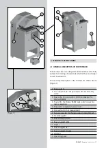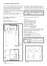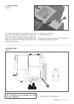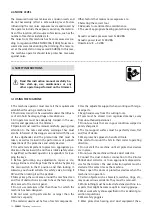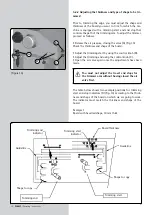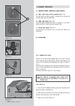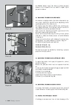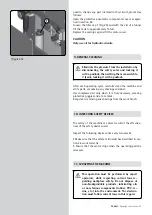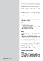
Check the bits: Before proceeding with the trimmer ad-
justment, make sure that the bits mounted on the machine
are appropriate for the finish that you wish to apply to the
edge. If they are not, replace them, following the instructions
in section 7.2 CHANGING THE EDGE TRIMMER BITS, in this
manual.
The machine leaves the factory with R. 2 and 10º bits
(8540183), and with the trimmer set for these bits, and
for a 2 mm edge. In other words, with the counter in the
table set to “0.”
5.2.1 Adjusting the cutter bit
To adjust the position of a particular bit, set the digital coun-
ter for the end position to the value shown in table (A), ta-
king into account the following indications:
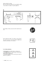
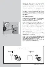
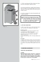
To bring the bit closer or move it farther away from the board
surface, use knob (B) (Fig. 13) situated on the side of the ma-
chine, releasing the safety wing screw (A) first.
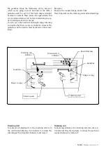
By turning the knob (B) clockwise, the board moves closer to
the bit, as indicated by the adjustment diagram (B) shown
below.
By turning the knob (B) counterclockwise the board moves
farther away from the bit, as indicated by the adjustment
diagram (B) shown below.
Once set to the values in the table, if the edge trimming is
not to your complete satisfaction, you may make small read-
justments, using the same method.
To prevent errors due to the normal play of the knobs, when
setting a measurement, for example, 0030, you must pass this
number and reach 0040, and then back to 0030.
After completing the adjustments, tighten the wing screw (A)
again to prevent the stop accidentally moving.
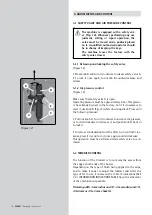
(Figure 13)
B
A
ADJUSTMENT DIAGRAM B
PAE85T
/ Operating instructions - 37
Summary of Contents for PAE85T
Page 71: ......

