6. MACHINE OPERATION
6.1 CONTROL PANEL FUNCTIONS, MAIN SWITCH
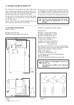
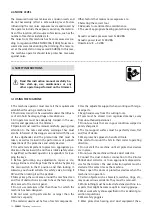
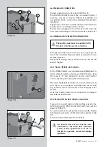
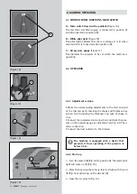
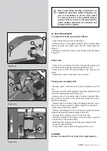
A - Main switch closed with a padlock (
Figure 16
)
The machine’s electrical supply is connected in position (I)
and disconnected in position (O).
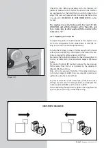
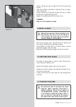
B - White pilot light
(Figure 18)
This pilot light indicates that there is voltage. It is lit when
main switch A is connected and in position (I).
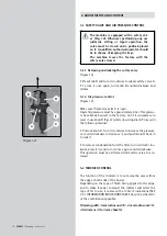
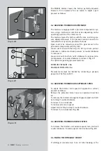
C - Air pressure gauge
(Figure 17)
This indicates the pressure in bar at which the machine is
operating.
6.2 OPERATION
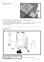
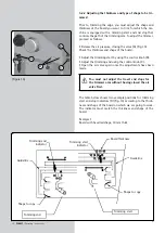
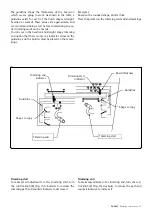
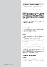
(Figure 19)
(Figure 16)
E
0
I
A
D
(Figure 17)
C
B
(Figure 18)
6.2.1 Adjustment revision
• Make the corresponding adjustments to the start and end
of the trimmer path, checking the shape and thickness. See
section 5.6.3 Adjusting the thickness and type of shape to
trim.
• Connect the compressed air connection and check the pres
-
sure on the pressure gauge, as indicated in section 4.4: Pneu-
matic connection.
• Connect the dust collector to the trimmer.
The machine is equipped with a device that
prevents it from operating if the pressure is
below 4 bar.
6.2.2 Start-up
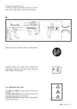
1 - Turn the switch (A) (Fig. 16) to position (I). The white pilot
light will come on (C) (Fig. 18)
2 - Place the board on the table so that it is flush with the rod
(E) (Fig. 19) and resting on the side bar (D).
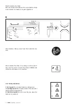
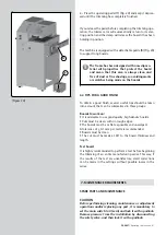
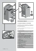
3 - Open the air valve A (Fig. 15).
40 -
PAE85T
/ Operating instructions
Summary of Contents for PAE85T
Page 71: ......

