
5
head of the machine at an angle, is supplied with the UC317S device.
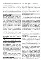
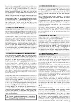
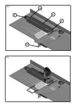
To mount the 1746268 special template guide on the router (Fig. 7), you
must insert it from the bottom. There is no need to remove the screws
and washers (P). Once in the centre, turn it to place it in its secured
position. Tighten the screws (P) firmly into this position.
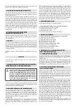
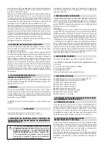
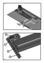
5.6. MOUNTING THE ROUTER
Rest the router on the base of the channel routing device and position
the equipment in the appropriate operating direction.
Insert rod (Q) (Fig. 8) into the holes on the base of the router, ensuring
that the two stops (R) are in place on both ends of the base and the
tightening studs face outward (Fig. 8). Next, insert the ends of the
rod into the hole and the groove located on the sides of the channel
routing device. Using the service key, tighten the fastening screw (S)
and the two stops (R) in the correct support position for the channel
routing device (Fig. 8).
To make the operation more comfortable, one of the handgrips (T)
may be removed from the router and placed on the front of the
machine (Fig. 8).
5.7. PREPARING THE UC317S CHANNEL ROUTING DEVICE
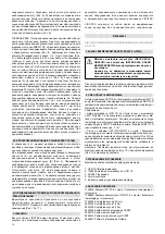
CHANNEL LENGTH: The maximum channel length that can be milled
with this device is 400 mm. If you wish to make channels or any other
type of grooves that are shorter in length, loosen the stops (R) and slide
them to the desired measurement (Fig. 8). Use the regulation found on
the channel routing device as an indicator for moving the stop (R).
The centre position of the cutting bit at the beginning and the end of
the maximum milling path is indicated by the position arrows, located
in each of the operating directions. The arrows only indicate the centre
of the cutting bit when the machine is in the vertical position.
CHANNEL SLOPE: To adjust the height of the channel routing device,
unlock the four locking screws (U) using the service key and raise or
lower the channel routing device by hand until it reaches the desired
height (Fig. 9). Retighten the four screws into the desired position.
With the channel routing device at its highest position, the difference
in height between the beginning and the end of the channel is 4 mm
if a 400-mm channel is made. The required channel slope must be
determined according to the part thickness and the channel length,
using the graduated ruler found on both sides of the equipment as
a guide (Fig. 9).
CUTTING DEPTH: After determining the slope of the channel, the cutting
depth must be set on the milling machine, following the instructions
found in the operating manuals for the FRE317VD router.
Rest the machine on the surface of the channel routing device on its
shortest side and adjust the tool blade until it is perfectly flush with
the part to be worked on (Fig. 8). Secure the machine in this position
with the locking lever (V) (Fig. 8). Loosen the fastening knob (W) and
lower the depth rod (X) until it presses against the lower step of the
revolving turret (Fig. 8). The entire fine adjustment rod (Y) must be
located on the exterior in order to make use of its entire distance. The
nut and locking nut (Z) must be positioned a few millimetres above
the lower stop to enable later adjustments to be made. In this position,
turn the fine adjustment depth indicator A1 (Fig. 8) until position
“0” matches the reference mark. This will be the starting position,
indicating the point at which the cutting bit comes into contact with
the material. Secure the adjustment rod firmly in place with fastening
knob (W), release the locking lever (V) and leave the machine in its
resting position.
Adjust the desired cutting depth of the tool, moving the fine adjustment
rod (Y) up by turning the fine adjustment knob (A2). A full turn of the
knob moves the fine adjustment rod 1 mm, with a maximum distance
of 5 mm. Each division in the gauged fine adjustment indicator (A1)
represents an advance of 0.1 mm.
Once the equipment is ready, move the machine to its starting position
at the beginning of the channel. Start up the machine and lower the
cutting tool until the rod presses against the revolving turret, and
then lock the height of the machine with the locking lever (V). For
absolute safety, the machine must be secured using the A3 nut and
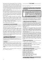
left to right, the minimum distance from the rail to the inside edge of
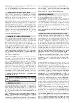
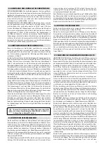
the sink is approximately 60 mm (Fig. 4).
Once you have determined the correct position of the rail, fasten it to
the part with suction pads or clamps, as appropriate.
5.3. FASTENING THE RAIL TO THE COUNTERTOP
WITH CLAMPS: To fasten the rail to the countertop, we recommend
using the clamps (H) provided with the UF317S/UFN317S accessory.
Insert a clamp into the slot of the rail through one end, move it closer
to the part and fasten it at the edge (Fig. 1 and 2).
WITH SUCTION PADS: The rail may also be fastened onto the countertop
using suction pads (I), but only when the surface of the part is flat,
smooth and non-porous (Fig. 1 and 2). To mount the suction pads on
the rail, insert the screws into the groove provided and fasten it with
wing screws (J) (Fig. 1). We recommend mounting the suction pads near
the edge of the rail. The suction pad works by pressing it down onto
the surface on which it is to be attached and moving the central lever
to the horizontal position. If the work is not performed continuously,
with long breaks in between, it will be necessary to check the suction
of the cups before resuming work.
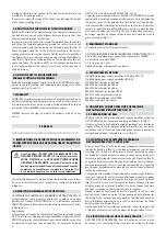
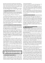
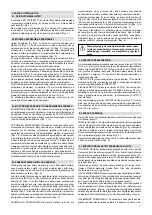
5.4. SECURING THE CHANNEL ROUTING DEVICE
Before moving the template equipment into position in order to mill
the first channel, you must determine whether you have enough space
on the dish drainer to fasten it in place by applying a suction pad (K)
directly onto the base of the channel routing device (Fig. 2).
If so, place the suction pad on the base of the template assembly and
fasten it using screws (M) (Fig. 2). To mill the first channel, loosen the
tightening knob (E) (Fig. 1) and position the template equipment over
the centre of the sink, sliding the fixing clamp on the rail. Use the
pointer of sight (N) on the fixing clamp as a reference when moving
the equipment along the millimetre ruler (B) (Fig. 1). Tighten fastening
knob (E) firmly. Next, lock the equipment in place by pressing suction
pad (K) down on the surface of the part and lift its central lever to
the horizontal position (Fig. 2).
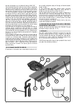
SUCTION PAD ADAPTER: On small-sized countertops, if you do not
have enough space to place the suction pad directly on the base of
the channel milling machine, you may secure the equipment in place
with the suction pad found on the side of the channel routing device
and using the suction pad adapter (O) (Fig. 5). To do so, secure it firmly
in place using screws (M) and place the suction pad (K) on the side
of the adapter located on the inside of the countertop. Use the wing
screws (J) (Fig. 5) to fasten the suction pad to the adapter (O) (Fig. 5).
If you are using the suction pad adapter (O) to secure the equipment,
we recommend that you operate the machine from right to left in
order to make better use of the space. To do so, you must mill the first
channel in the position closest to the outer edge of the sink in order
to ensure that the machined channels never interfere with the grip
of the suction pad (Fig. 6).
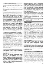
Before proceeding to mill the channels, make sure that
the accessory is firmly attached to the countertop at
all working positions.
5.5. PREPARING THE ROUTER
The most appropriate cutting tool for milling the dish drainer channels
is the 1740324 10-mm R corner trimmer that is provided with the
FRE317VD router, or the optional 1740322 5-mm R trimmer. To use
this cutter bit, hold the head of the milling machine at an angle of at
least 10º, following the instructions in the operating manual for the
FRE317VD router.
With the machine at a 10º angle, mount the selected tool, following the
instructions found in the operating manual for the FRE317VD router.
The FRE317VD router is guided along the UC317S equipment by the
1746268 special template guide, with a diameter of 30 mm and open at
the front. This template guide, specially designed for operating with the
Summary of Contents for UC317S
Page 19: ...19 Fig 2 K H M Fig 3 170 mm F G ...
Page 20: ...20 Fig 5 Fig 4 60 mm K J M O ...
Page 21: ...21 Fig 6 Fig 7 P ...
Page 22: ...22 Fig 8 R Q T X A1 A2 A3 V Z U Y W S Fig 9 U ...
Page 23: ...23 Fig 10 Fig 11 ...


