flowscreen
Operating Instructions
22 / 24
Version 1.0
Copyright ©
3.11
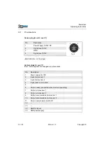
Pin allocations
Sensor plug (2 and 3, see 3.1)
(Flash direction: on the plugs)
System plugs (4, see 3.1)
Input / output signals are arranged as optocouplers.
Pin
Description
1
Power supply 10-30V DC
2
Signal input 0-10V
3
GND
4
Signal input 0-10V
Pin
Description
1
Power supply 24V DC
2
Input, start sensor 1
3
Input, start sensor 2
4
Input, reset error counter
5
- -
6
Output, ready (connected when device is operating)
7
Output, error sensor 1
8
Output, error sensor 2
9
Output, accumulated errors sensor 1
10
Output, accumulated errors sensor 2
11
Output, overpressure switch-off
12
- -
13
- -
14
GND for inputs
15
GND power supply
1
2
3
4
Fig. 9
Summary of Contents for flowscreen
Page 1: ...Operating Instructions flowscreen ...
Page 2: ......

