background image


- 22 - 


d)


Repeat  above  procedure  with  several  random 
bridge  unbalances  to  achieve  best  average 
performance.  (If reading the ±10V output with a 
DVM,  readings  at  “balance”  ideally  should  be 
between  0  and  –3  mV,  which  is  the  theoretical 
resolution of the circuit at these settings.) 

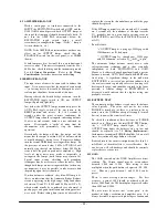
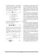
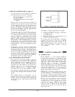
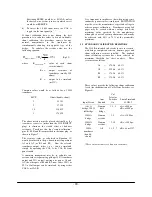
Adjustments H, L, M and Y (C31) all affect common-
mode  rejection  in  the  preamplifier.    They  are  most 
conveniently set using an audio oscillator (10 Hz to 5 
kHz): 

a)


Connect the oscillator between circuit ground and 
the  two  amplifier  inputs  (INPUT  pins  A  and  J) 
shorted  together.    Set  the  oscillator  for  about  10 
Vp-p (3.5 Vrms). 

b)


Connect  oscilloscope  to  ±10V  (TP7)  output,  ac-
coupled. 

c)


Set GAIN dial at 1.000 and press X1 button. 

d)


Set oscillator at 10 Hz; adjust M for best null on 
scope. 

e)


Set oscillator at 1 kHz; adjust L for best null. 

f)


Repeat (d) and (e) if adjustments were required. 

g)


Press X100 GAIN button. 

h)


Set oscillator at 10 Hz; adjust H for best null. 

i)


Set  oscillator  at 1  kHz;  adjust  capacitor  Y  (C31) 
for best null. 

j)


Repeat (h) and (i) if adjustments were required. 

k)


If  (h)  and  (i)  required  significant  adjustment, 
repeat from (c) on. 

7.2


BATTERY REPLACEMENT


The  current  drain  from  the  keep-alive  batteries  in  the 
automatic  bridge  balance  circuit  is  continuous  with 
POWER  off,  whether  the  instrument  is  plugged  in  or 
not,  but this  current  is  so  small  5  to 10  nA)  that  self-
discharge (i.e., shelf-life) is far more significant. 

The  batteries  should be  replaced when  the  test  circuit 
indicates  low  voltage  (see 

4.11  Battery  Test

),  or 

routinely two years after installation. 

The  batteries  used  in  the  2310B  are  widely  used  and 
are  available  at  most  electronic  supply  stores.     Eagle 
Picher PT-2150  (Lithium  3.6Volt,  1/2AA)  or  equal  is 
recommended  for  a  replacement.    Any  of  the 
following  silver  oxide  batteries  may  be  used  (two 
required): 

To replace the battery: 

a)


Disconnect  power  and  remove  cover  on left  side 
of the 2310B. 

b)


Locate  the  battery  holder  near  the  rear  of  the 
2310B. 

c)


Note the orientation of the existing battery. 

d)


Remove  and  properly  dispose  of  the  old  battery 
in accordance with local codes. 

e)


Install the new battery with the positive end (case 
of cell) toward the rear of the instrument, and the 
negative end toward the front. 

f)


Replace 2310B side cover. 

g)


Apply  ac  power  to  the  2310B  and  press  BAT 
TEST; the + OUTPUT lamp should light. 

7.3


COMPONENT REPLACEMENT


It is recommended that a defective 2310B be returned 
to  Vishay  Micro-Measurements  for  factory  service, 
especially during the warranty period (to preserve the 
warranty);  however,  a  qualified  technician  can  often 
repair  the  unit  in  the  field.    Most  electronic 
components used are standard commercially available 
items.  Any component can be purchased from Vishay 
Micro-Measurements 

(if 

the 

Vishay 

Micro-

Measurements part number is not listed below, please 
provide  us  with  the  component  symbol  and  value  — 
or  an  adequate  description  of  the  part  —  and  the 
instrument serial number). 

The  following  information  may  be  of  value  for  field 
service. 

7.3a Resistors: 

The  1%  resistors  are  generally  100  ppm/°C,  and 
0.1% values are generally 25 ppm/°C). 

All  0.05%  and  tighter  tolerances  are  Vishay 
SMR1DR  (2 ppm/°C)  and  must be  ordered  from 
Vishay Micro-Measurements. 

Resistors R71 through R74 are part of the bridge 
completion assembly and must be ordered as part 
200-131240. 


7.3b Connectors   


  Symbol     P/N


Input plug, 15-pin    
 [Bendix PT06A-14-15P(SR)] 

P5 

12X300531 

Mating power plug (not supplied) 

 (ITT/Cannon DA15S or equal) 

— 

12X300151 

Remote cal plug (for 2350/2360) 
 (Cinch-Jones S-308-CCT) 

— 

12X300533 

Line cord (for 2350 and 2360) 
 (Belden 17742) 

— 

21X300126 


7.3c Battery


Keep-alive supply 
 (Eagle Picher PT-2150) 

B1 

23X500004 
(1 required) 


7.3d Toggle Switches


Filter selector (on p.c.b.) 
 (Grayhill 76TC03) 

SW1 

10X900046 

Excitation sense selector 
 (on p.c.b.) (Grayhill 76TD01) 

SW5 

10X900047 

Summary of Contents for 2310B

Page 1: ...ditioning Amplifier 2310B Instruction Manual Vishay Micro Measurements P O Box 27777 Raleigh NC 27611 United States Telephone 1 919 365 3800 FAX 1 919 365 3945 E mail vmm us vishaymg com www vishaymg com Oct 2009 130 000137 ...

Page 2: ...ONSIDERATIONS 8 4 5 OUTPUT CONNECTIONS 9 4 7 FILTER OUTPUT SELECTOR 10 4 8 EXCITATION 10 4 9 AMPLIFIER BALANCE 11 4 10 BRIDGE BALANCE 11 4 11 BATTERY TEST 11 4 12 GAIN 11 4 13 FILTER 12 4 14 DYNAMIC TESTING 13 4 15 TAPE PLAYBACK 13 4 16 REMOTE OPERATION RELAYS 14 4 17 QUARTER BRIDGE NONLINEARITY 14 5 0 SHUNT CALIBRATION 14 5 1 INTRODUCTION 14 5 2 SHUNT CALIBRATION COMPONENTS IN 2310 15 5 3 SHUNT C...

Page 3: ... 2 Complete 10 Channel 2300 System 2310 Signal Conditioning Amplifier Module with Stabilizer Accessory 4 channel System in 2360 Portable Enclosure 2350 10 Channel Rack Adapter ...

Page 4: ...nce for months without external power Dual polarity two step double shunt calibration Optional remote calibration and auto balance reset Playback mode to filter and observe or re record previously recorded magnetic tape data And many other convenience features All specifications are nominal or typical at 23 C unless noted Performance may be degraded in the presence of high level electromagnetic fi...

Page 5: ...rred to input Noise gain over X100 all outputs 0 01 to 10 Hz 1 µV p p RTI 0 5 to 125 kHz 6 µVrms max RTI FILTER Characteristic Low pass active six pole Butterworth standard Frequencies 3 1 dB 10 100 1000 and 10 000 Hz and wide band Outputs filtered either one or both switch selected on p c board AMPLIFIER OUTPUTS Standard output 10V 5 mA min Tape output 1 414V 1 Vrms 5 mA min Linearity dc 0 02 Eit...

Page 6: ...ircuit to seek a new balance point The prior stored balance point is replaced The HI lamp yellow LED lights when the automatic balance circuit is in its high range it indicates a bridge unbalance exceeding 1 If the unbalance exceeds 5 this lamp will cycle on and off continuously TRIM Control A vernier control to refine bridge balance when desired Normally the automatic balance circuit will achieve...

Page 7: ...filter circuits if selected on the front panel and post amplifiers Full scale input is 1 4V Both outputs are operable NOTE This recessed switch must be returned to the NORM position to monitor incoming signals at the INPUT connector 10V Connector A coaxial BNC connector for the 10V Output of the amplifier The 10V Output is typically connected to oscilloscopes DVM s analog multiplexers etc TAPE Con...

Page 8: ...ine voltage neutral or common Green or green yellow Earth ground 4 2 GAGE INPUT CONNECTIONS It is suggested that the 2310B be turned on press the red POWER button and allowed to stabilize while preparing the input connectors To prevent powering the input bridge circuits at this time turn the EXCITATION rotary switch to 0 7V and the toggle switch to OFF 4 2a Each amplifier uses a separate input plu...

Page 9: ... connection than chassis ground but to be effective the shield must be left disconnected and insulated against accidental groundings at the gage end Normally the guard shield is used inside a conventionally grounded shield as shown in Figure 2C Certain important considerations affect wiring technique depending on whether the purpose of the test is to measure static or dynamic data 4 4a Dynamic Dat...

Page 10: ...rcuit usage will often cause the 10V outputs to approach 15V Tape output is limited to 2V The GALV output could deliver over 20 mA If such levels can damage the output devices it is important that proper precautions be taken In those situations it is suggested that external resistance be added to the output circuitry Normally the third prong on the power cord should establish an adequate chassis t...

Page 11: ...commercial transducers the manufacturer usually specifies the bridge excitation If the transducer uses metallic foil gages this is a maximum value while any excitation up to the maximum could be used generally 50 to 75 of this maximum will yield improved transducer stability while retaining a good signal to noise ratio However when using transducers with semi conductor piezoresistive gages the spe...

Page 12: ...ween 1 and 5 5000 and 25 000 µε at GF 2 which would usually be considered very abnormal if quality gages and good installation and wiring practices were used Before taking data it may be advisable to explore the reason for this unbalance possibly the gage should be replaced If the HI lamp constantly cycles on and off 4 seconds on 4 seconds off the unbalance at the input exceeds 5 probably due to a...

Page 13: ...ile simple in concept there are so many subtleties alternate circuits available in the 2310B and equations that the user is referred to in 5 0 Shunt Calibration of this manual which is devoted exclusively to this topic When using transducers it is often most accurate and convenient to simply apply a known input force torque pressure etc and adjust GAIN to achieve the desired output If this physica...

Page 14: ...O BAL must be OFF all the way up and the selection of GAIN button and EXCITATION must be made very carefully so as not to exceed the limits tabulated above 4 15 TAPE PLAYBACK The 2310B Amplifier can be used to re examine data previously recorded on magnetic tape A suggested practice is to originally record the data with no filter on the TAPE output TAPE FILTER selector toggle on the p c board set ...

Page 15: ...cautioned regarding uncertainty of the value of gage factor above 1 strain If it is desired to obtain an output which is linear with R in one arm of a bridge this can be achieved with the 2310B This technique utilizes the remote sense leads to maintain constant voltage across a dummy resistor and therefore constant current through this resistor and through the active arm Connections to the INPUT p...

Page 16: ...internal dummy gages D120 and D350 5 3 SHUNT CALIBRATION STRESS ANALYSIS Shunt calibration can be achieved by shunting any one of the four arms of the input bridge this includes the active gage and the bridge completion arms in the 2310B The same equation applies but note the definition of Ra 6 10 a cal a cal R R K R µε Eq 10 where µε cal strain simulated microstrain Ra resistance of leg shunted o...

Page 17: ...SADVANTAGES Two added wires necessary Simulates compression only CKT 4 Shunt Active Half Bridge Excitation SENSE LOCAL Cal Selector Switches 2 closed P to R1 4 closed P to R2 8 closed S to R4 Others open down Ra gage resistance K K USE Half or full bridge ADVANTAGES Classic theory using any leadwire method except resistance between active gages but be negligible Simulates and DISADVANTAGES Three a...

Page 18: ... normal output lead Since the effects of leadwire resistance are very measurable additional leads dedicated to the shunt calibration circuit must be used between the transducer connector and the INPUT connector to the 2310B The complete schematic of the available connections for shunt calibration of transducers is shown in Figure 7 As an example of transducer shunt calibration assume that the cert...

Page 19: ...AL B front panel switch A common arrangement may be to calculate two resistor values representing perhaps 100 transducer output and 25 output putting one pair at A1 and A2 the other pair at B1 and B2 now either 100 or 25 of full output can be simulated by using either CAL A or CAL B It is important to emphasize that when using semi conductor piezoresistive transducers EXCITATION must be set at the...

Page 20: ...imately reach the same slope at high frequencies the sharpness of the Butterworth filter at FCO results in better attenuation at any given high frequency c Should there be an instantaneous step input the Butterworth filter will produce 5 to 8 overshoot assuming precise component values whereas the Bessel filter has no overshoot Thus the choice of characteristic is very dependent on the type of tes...

Page 21: ... identical filters to avoid data skew caused by different time delays in the three channels Maintenance is to be done only by qualified technicians 7 1 ADJUSTMENTS To assist in maintenance the following the diagram is provided to indicate the position of the IC and adjustments that are used to calibrate the 2310B Also shown are the relays used for shunt cal and zero functions Schematic diagrams ar...

Page 22: ...ns from one end EXCITATION at OFF and AC coupling button out for dc coupling Also the front panel settings listed at right must be made prior to adjustment and not changed unless subsequently directed to do so Auto Balance adjustments should be made with a 350Ω bridge connected to the input it should be possible to unbalance this bridge randomly up to about 3 unbalance METER LEAD FRONT PANEL ADJUS...

Page 23: ...uired To replace the battery a Disconnect power and remove cover on left side of the 2310B b Locate the battery holder near the rear of the 2310B c Note the orientation of the existing battery d Remove and properly dispose of the old battery in accordance with local codes e Install the new battery with the positive end case of cell toward the rear of the instrument and the negative end toward the ...

Page 24: ...5A fast acting Littelfuse 251 250 UL CSA Vishay M M 18X300007 Model 2350 2360 A power fuse is located on the rear panel The following lists the recommended time lag fuse ratings 2350 UL CSA T 1 A IEC T 8 A 2360 UL CSA T 5 A IEC T 4 A APPENDIX 1000 OHM BRIDGE COMPLETION The 2310B Signal Conditioning Amplifiers provides the capability of 1000 ohm quarter bridge operation For this mode the 120 ohm du...

Page 25: ...sulting from personal injury Some states do not allow the exclusion or limitation of incidental or consequential damages for consumer products so the above limitations or exclusions may not apply to you The purchaser agrees that the Purchaser is responsible for notifying any subsequent buyer of goods manufactured by Vishay Micro Measurements of the warranty provisions limitations exclusions and di...

Reviews: