Technical Manual
7-14
Digital Inputs
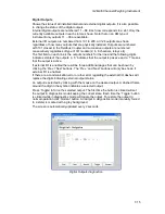
Shows the status of all installed internal and external digital inputs.
Internal digital inputs are numbered 11 – 68. Each row corresponds to a slot. Only the
currently available inputs in each slot are shown. Note that on an RM type of
instrument only inputs 11 – 38 are available.
External I/O inputs are numbered from 101 to 228. All 128 inputs are shown regardless
of how many inputs that are physically installed. Inputs are numbered with 101 closest
to the Fieldbus Coupler and successive inputs are numbered consecutively regardless
of type of I/O module (2, 4, 8 channels, etc).
The first field on each line is the input numbers for the line and the following digits
indicates status of the inputs. A ‘0’ indicates that the input is passive and a ‘1’ means
that the input is active.
If external I/O is enabled there will be three additional pages that can be shown by
pressing the ‘Prev.’/’Next’ buttons or arrow left/right buttons. The ‘Prev.’ and ‘Next’
buttons will only be shown if external I/O is enabled.
If there are a communication error or other error regarding the external I/O dashes will
replace the digits indicating external input status.
The screen is automatically updated every 2 seconds.
Digital Inputs diagnostics.
Summary of Contents for G4
Page 2: ......
Page 18: ...Technical Manual 1 14 ...
Page 39: ...G4 Multi Channel Weighing Instrument 3 7 ...
Page 104: ...Technical Manual 5 18 ...
Page 158: ...Technical Manual 6 54 ...
Page 178: ...Technical Manual 7 20 ...
Page 186: ...Technical Manual 8 8 ...
Page 196: ......
Page 197: ...G4 Multi Channel Weighing Instrument Appendix 1 ...
Page 198: ...Technical Manual ...
Page 199: ......


