Technical Manual
2-10
DIO8
The voltage levels on connectors of I/O modules shall not exceed hazardous
voltage levels of 30 Vrms, 42.4 Vpeak or 60 Vdc under normal conditions. In
wet locations these voltage levels shall not exceed 16 Vrms, 22.6 Vpeak or
35 Vdc.
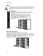
Digital inputs
Terminals 11 – 18 and terminal 19 (ICom) as a common connection.
Eight digital inputs are provided, with functions that can be set
in the G4 set-up.
External sourcing (24 V
) from the instrument power supply
(max. 100 mA) or from a separate DC supply must be used.
Note that either the positive or the negative pole of the voltage
source (24 V
) can be connected to ICom (19).
Shielded cable/cables must be used, with the shield connected
to terminal 20.
I1
I2
I3
I4
I5
I6
I7
I8
ICom
Shield
-
-
+
+
11
12
13
14
15
16
17
18
19
20
24 V
Solid state relay outputs
Terminals 1 - 8 with terminal 9 (OCom) as a common connection.
Eight digital (relay) outputs are provided with contact rating given in Technical data.
External sourcing (24 V
) from the instrument power supply (max. 100 mA) or from a
separate DC supply must be used. Note that either the positive or the negative pole of
the voltage source (24 V
) can be connected to OCom (9).
Shielded cable/cables must be used, with the shield connected to terminal 10.
O1
O2
O3
O4
O5
O6
O7
O8
OCom
Shield
Load
Load
Load
Load
Load
Load
Load
Load
+
-
+
-
1
2
4
3
5
6
7
8
9
10
24 V
!
Summary of Contents for G4
Page 2: ......
Page 18: ...Technical Manual 1 14 ...
Page 39: ...G4 Multi Channel Weighing Instrument 3 7 ...
Page 104: ...Technical Manual 5 18 ...
Page 158: ...Technical Manual 6 54 ...
Page 178: ...Technical Manual 7 20 ...
Page 186: ...Technical Manual 8 8 ...
Page 196: ......
Page 197: ...G4 Multi Channel Weighing Instrument Appendix 1 ...
Page 198: ...Technical Manual ...
Page 199: ......


