background image

X6100/6200 

Assembly

Page 6

NOTE: Assembly Step 3 refers to Model X6100 only. 
For Models X6200/ X6200HRC proceed to Step 4 for Console
Mast installation.

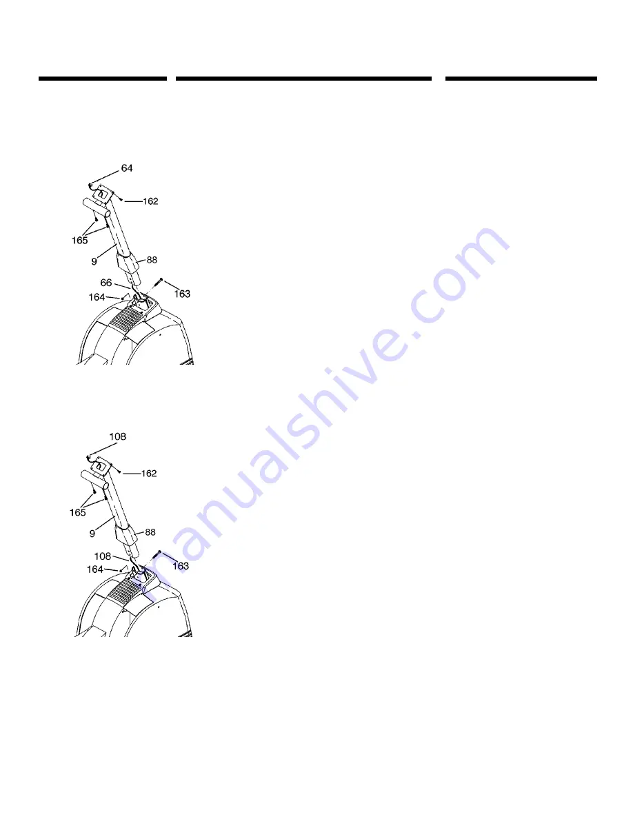
Step 3 • Console Mast - 

Model X6100 only

1: Unfold the RPM Sensor Wire (64) that is folded into the Frame 

Console Mast bracket. Straighten this cable and remove any 
kinks by drawing the cable through your fingers.

2: Slide the Rubber Console Mast Cover (88) onto the Console 

Mast (9) until it is above the first waterbottle screw.

3: Holding the Console Mast (9) above the Frame Console Mast 

Bracket, guide the RPM Sensor Wire (64) and Lower Magnet 
Shift Cable (66) through the Console Mast while 
simultaneously sliding the Console Mast onto the frame 
bracket.

4: Bolt the Console Mast (9) to the frame using the two Console 

Mast Attachment Bolts (163) and Nuts (164). Make sure these 
bolts are very tight. Now slide the Rubber Console Mast Cover 

(88) back down to cover the bolt heads.

NOTE: Assembly Step 4 refers to Models X6200/ X6200HRC only.
For Model X6100 proceed to Step 5 for Handrail installation. 

Step 4 • Console Mast - 

Models X6200/ X6200HRC only.

1: Unfold the Console Cable (108) that is folded into the Frame 

Console Mast bracket. Straighten this cable and remove any 
kinks by drawing the cable through your fingers. Find the 
string that is attached to the inside of the Console Mast (9), 
but do not remove yet.

2: Slide the Rubber Console Mast Cover (88) onto the Console 

Mast (9) until it is above the first waterbottle screw.

3: Now attach the Console Cable (108) to the string located 

inside the Console Mast. Holding the Console Mast (9) above 
the Frame Console Mast Bracket, guide the Console Cable 
(108) through the Console Mast while simultaneously sliding 
the Console Mast onto the frame bracket.

4: Bolt the Console Mast (9) to the frame using the two Console 

Mast Attachment Bolts (163) and Nuts (164). Make sure these 
bolts are very tight. Now slide the Rubber Console Mast Cover 

(88) back down to cover the bolt heads.

Summary of Contents for X6100

Page 1: ...box lay them out and review the parts list If any parts are missing please call 1 800 335 4348 Ext 12 Before proceeding find your Elliptical Trainer s serial number located on the frame between the folding pedal arm guide rails and enter here ______________________________ Refer to this number when calling for service I T A L L S T A R T S W I T H A V I S I O N A62 2 ...

Page 2: ...X6100 6200 Parts Diagram Page 2 ...

Page 3: ... Bolts 6 20mm L x 8mm D Pedal Arm Guide Rail Parts 7 Pedal Arm Guide Rails 2 Pedal Arm Parts 64 Pedal Arms 2 173 Pedal Arm Attachment Bolts 4 164 Pedal Arm Attachment Nuts 4 72 Pedal Arm Foot Pads 2 73 Foot Toe Pieces 2 99 Foot Toe Piece Locking Knobs 2 Console Parts 9 Console Mast 1 163 Console Mast Attachment Bolts 2 164 Console Mast Attachment Nuts 2 88 Rubber Console Mast Cover 1 15 Console 1 ...

Page 4: ...uide Rail Assembly All Models 1 Slide the Rear Foot Axle 96 through the Rear Foot Nylon Sleeves 98 2 Place a Wavy Washer 95 over each end of the Rear Foot Axle 96 3 Slide the Pedal Arm Guide Rails 7 onto the Rear Foot Wheel Axle 96 4 Place the Inside Wheel Washers 166 on the Rear Foot Wheel Axle 96 5 Slip the Rear Transport Wheels 97 onto the Rear Foot Wheel Axle 96 and secure them with the Outsid...

Page 5: ...of the Right Pedal Arm 61 and secure using the two Pedal Arm Attachment Bolts 173 and the two Pedal Arm Attachment Nuts 164 2 Repeat the above step with the Left Pedal Arm 3 Place the Pedal Arm Foot Pads 72 on the Pedal Arms 64 4 Place the Foot Toe Pieces 73 on the Pedal Arms 64 securing them with the Foot Toe Piece Locking Knobs 99 ...

Page 6: ... Cover 88 back down to cover the bolt heads NOTE Assembly Step 4 refers to Models X6200 X6200HRC only For Model X6100 proceed to Step 5 for Handrail installation Step 4 Console Mast Models X6200 X6200HRC only 1 Unfold the Console Cable 108 that is folded into the Frame Console Mast bracket Straighten this cable and remove any kinks by drawing the cable through your fingers Find the string that is ...

Page 7: ...cated on the Console Mast just below the Console 3 Slide one end of the Left Lower Hand Rail 79 into the Left Upper Hand Rail 76 and the other end into the Lower Hand Rail Support located on the lower portion of the Frame just ahead of the Rear Transport Wheels 97 4 Secure the Hand Rail together using the three Hand Rail Attachment Bolts 165 5 Repeat the above steps for the Right Hand Rail assembl...

Page 8: ...the tab out and discard 3 Press the Console Mast Cover 225 into the opening of the Console Mast 9 NOTE Always read the Owner s Manual before operating your Vision Fitness Elliptical Trainer Step 8 Install Batteries and Test Operation Model X6100 only 1 Remove the battery compartment lid on the back of the Console 15 and install the Batteries Two C cell batteries are required 2 Use arrows on Consol...

Page 9: ... at the front of the Elliptical Trainer just above the Front Transport Wheels Plug the Power Supply 207 into an electrical outlet and begin testing procedures NOTE Always read the Owner s Manual before operating your Vision Fitness Elliptical Trainer Step 10 Operation Test Models X6200 X6200HRC only Run this simple optional test prior to using 1 Choose Intervals program Level 16 2 Choose Time of 0...

Page 10: ...placing the belt against your chest This moisture will allow the signals to be conducted to the transmitting hardware If you ever use the bike and the display does not show a heart rate value remoisten the electrodes 2 You will get the best results if you wear the transmitter directly against your skin Once these electrodes are moistened center the transmitter just below the breast or pectoral mus...

Page 11: ...ceiving mechanism on the underside of the Pedal Arm Firmly push the Guide Rail until it clicks and locks into position B Check that it is secure before proceeding Repeat these steps with the other Pedal Arm and Guide Rail to completely fold your Elliptical Trainer for compact storage 4 To unfold your Elliptical Trainer push the recessed lock button found on the underside of one Guide Rail A Carefu...

Page 12: ...621 D East Lake Street P O Box 280 Lake Mills WI 53551 920 648 4090 ...

Reviews: