Unitronics
1
Vision™ OPLC™
Installation Guide
V290 (Color)
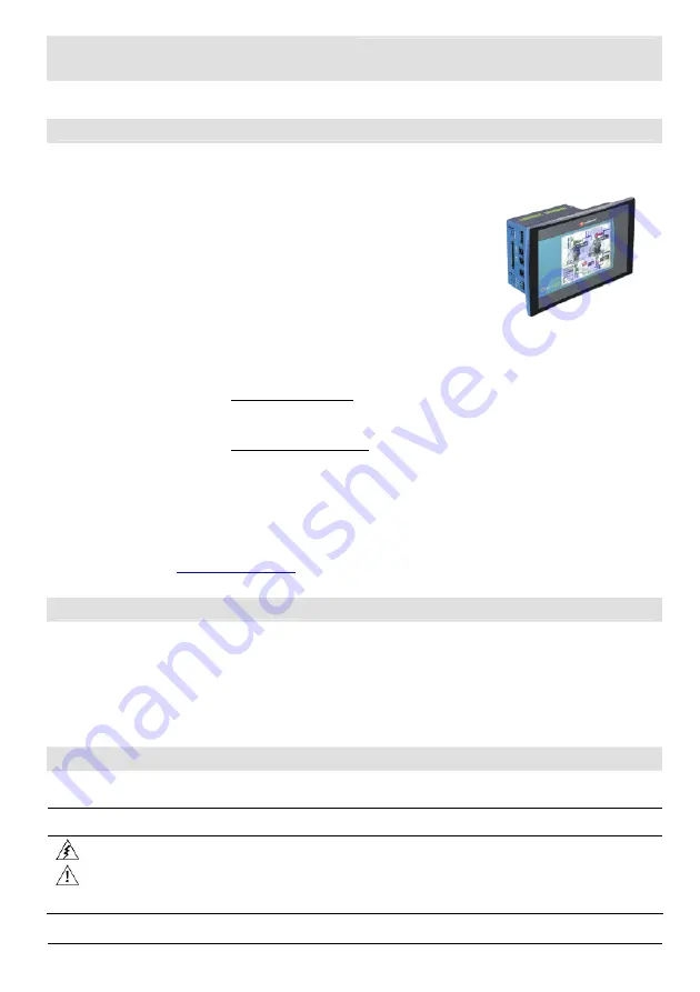
This guide provides basic information for Unitronics’ LCD color touchscreen models
V290-19-C30B and V290-19-T40B.
General Description
Vision OPLCs are programmable logic controllers that comprise an integral operating panel.
Operating panel features differ according to model.
The V290-19-C30B and V290-19-T40B offer a color touchscreen,
which displays a virtual keyboard when the application requires the
operator to enter data.
Communications
2 isolated RS232/RS485 ports
and a CANbus port.
The user can order and install an
additional port. Available port
types are: RS232/RS485, and
Ethernet.
V290 (Color Screens)
Touchscreen only
I/O Options
Vision supports up to 171 digital, high-speed, and analog I/Os via modules.
Number of I/Os and types vary according to module.
Snap-in I/O Modules
Plug into the back of the controller to provide an on-board I/O
configuration.
I/O Expansion Modules
Via adapter, use up to 8 I/O Expansion Modules comprising up to
128 additional I/Os.
Programming
Write both the HMI and Ladder control application using VisiLogic freeware.
The Vision User Guide and the product’s technical specification sheet contain additional information.
These documents are located on the Unitronics’ Setup CD. They may also be downloaded from the
Technical Library at
www.unitronics.com
.
Standard Kit Contents
Vision controller
Programming cable + RS232 adapter
Mounting brackets (x4)
Grounding hardware
3 pin power supply connector
Rubber seal
5-pin CANbus connector
Unitronics’ Setup CD
CANbus network termination resistor
Danger Symbols
When any of the following symbols appear, read the associated information carefully.
Symbol Meaning Description
Danger
The identified danger causes physical and property damage.
Warning
The identified danger could cause physical and property damage.
Caution
Caution Use
caution.


