26
6
Operating Procedures for Parallel Systems
6th1
Introduction
Premium DSP UPS Systems are designed according to high MTBF figures with increased
reliability but in case of necessity, a second ( or more ) Premium DSP UPS’s can be connected in parallel
redundant configuration for supplying the very critical load to increase the reliability. Maximum 4pcs
identical power and specification Premium DSP can be connected in parallel.
If power demand increases in a certain UPS application exceeding the power rating of an already
installed stand-alone UPS, then a second (or more) UPS of the same model and power rating can be
added in parallel to the existing UPS to increase the output power capacity.
The AC inputs of all UPS’s in the parallel system are connected to the same mains, and all the AC
outputs are connected to each other. Each UPS has its own battery group. The critical load is connected
to the common output of the parallel system. There are also some signal cable connections between the
UPS units necessary for parallel operation, and will be described later.
6th2
Procedure for Commissioning and Start Up ( First Installation )
1) If the UPS’s will be converted to parallel systems on site, after installing the parallel kit to each ups,
calibration of them should be made perfectly at single mode initially.
2)
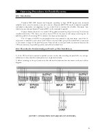
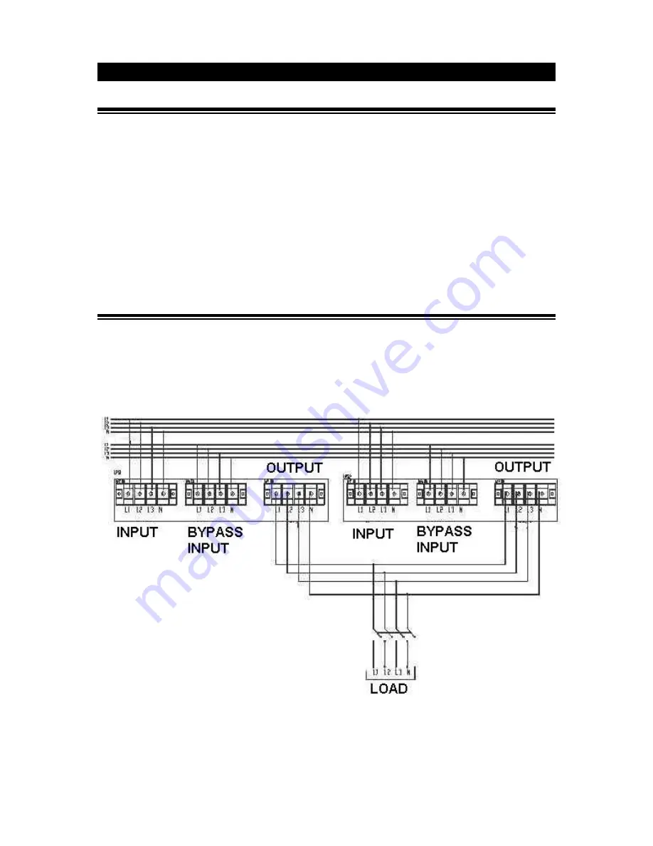
Before switching on the ups’s, make sure that electrical connections have been made as shown in below
diagram:
( OUTPUT CONNECTION OF PARALLEL UPS SYSTEMS )


