3.2.5 USB interface for advance programming
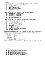
The V40-10HDMI provides a USB interface with the appropriate software for advanced programming. For more
information read Appendix A.
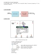
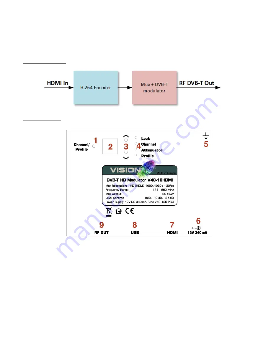
3.3 BLOCK DIAGRAM
3.4 FRONT PANEL
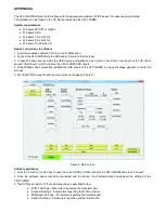
Figure 1. Front panel operating controls
1
.
Channel or Profile selection button
2
. Seven Segment Display (SSD)
3
. UP / DOWN buttons
4
. LED indicators
a.
Lock: ON when HDMI communication have been established
b.
Channel: ON when “Channel” mode is selected
c.
Attenuation: ON when “Attenuator” mode is selected
d.
Channel: ON when “Profile” mode is selected
5
. Ground connector
6
. +12 V DC power input
7
. HDMI input
8
. USB input
9
. RF OUT output


