background image

 
3.5 INSTALLATION


The V40-10HDMI can be programmed with one of the following ways: 


From the front panel display 


From the USB interface 

 
3.5.1 Installation using the Front panel display


The user is able to install very quick and easy multiple V40-10HDMIs using the SSD + Button interface of the front panel 
of the device, following the steps below: 

1

st

 Step


Power up the V40-10HDMI  by  connecting  the external power supply. The V40-10HDMI  will  need 20-30 seconds to 
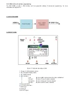
initialize itself. The SSD (Seven Segment Display – No2/Figure 1.) depicts the initialization status. 

2

nd

 Step


Choose “

Channel mode

” by pressing the Channel/Profile button (No 1 / Figure 1. ) and the “Channel LED” will be 

illuminated indicating that “Channel” mode is selected.  

3

rd

  Step


Choose “

Attenuation mode

” by pressing the Channel/Profile button (No 1 / Figure No.1 ) the “Attenuation LED” will be 

illuminated indicating that “Attenuation” mode is selected. 

4

th

 Step


Choose “

Profile mode

” by pressing the Channel/Profile button (No 1 / Figure 1.) and the “Profile LED” will be illuminated 

indicating that “Profile” mode is selected.  

How Profiles works


In an installation all the modulators (or Mux in general) need to have different values of the following fields to avoid 
conflicts in the automated scan of the TV sets: 
 

Program Name          


 Service ID    


TS ID


For that reason, the user must always select a different Profile number for  every modulator in the system starting from 
Number #1.  

Eg. Let’s say we want to install three modulators in a CATV network. In step No 4 we will choose: 


● Profile Νο 

1

 for the 

1

st

 modulator  


o meaning: Program Name = DTV 

1


o meaning: Service ID =  

1


o meaning: TS ID = 224

0


● Profile Νο 

2

 for the 

2

nd

 modulator  


o meaning: Program Name = DTV 

2


o meaning: Service ID =  

2


o meaning: TS ID = 224

1


● Profile Νο 

3

 for the 

3

rd

 modulator  


o meaning: Program Name = DTV 

3


o meaning: Service ID =  

3


o meaning: TS ID = 224

2


As a result, all the above modulators have different values in the above fields. 

Caution!!!


● Every time we choose a different Profile number, the 

V40-10HDMI will apply a full reset to itself that will last for 20-30 

seconds. 

● Using the USB interface

 enables the ability to add custom values to the above fields. 

3.5.2 Installation using the USB interface


The  V40-10HDMI  provides a USB interface with the appropriate software for advanced programming. For more 
information read Appendix A.  

Summary of Contents for V40-10HDMI

Page 1: ...V40 10HDMI HDMI to DVB T HD MODULATOR Operation Manual...

Page 2: ...s to cover any ventilation slots Only mount the modulator in vertical position with the RF connector at the bottom Always allow at least 10cm of free space around all sides of the modulator to aid ven...

Page 3: ...ply 3 2 1 Auto reset functions and watchdog During the normal operation of the V40 10HDMI the main CPU monitors all the internal parts in order to ensure that the device works normally In case of an i...

Page 4: ...gure 1 Front panel operating controls 1 Channel or Profile selection button 2 Seven Segment Display SSD 3 UP DOWN buttons 4 LED indicators a Lock ON when HDMI communication have been established b Cha...

Page 5: ...ode is selected How Profiles works In an installation all the modulators or Mux in general need to have different values of the following fields to avoid conflicts in the automated scan of the TV sets...

Page 6: ...rable Parameters TS ID Original Network ID Network ID Provider Name LCN support Yes LCN Providers Nordin ITC UK EICTA Europe New Zealand DVB T Output Standard EN 300 744 Bandwidth 5 6 7 8 MHz Mode 2K...

Page 7: ...contains the V40 10HDMI USB drivers 4 Once Windows has successfully installed the USB drivers of the V40 10HDMI a pop up message appears to verify this process 5 Run the DVProbe exe file and the main...

Page 8: ...Audio PID value 3 9 LCN No Set the LCN No 1 999 must be enabled first 3 10 LCN Provider Set the LCN provider Caution Modulation settings must be applied with care and in order to have adequate output...

Page 9: ...es Mbit s for 8 MHz bandwidth non hierarchical systems Modulation Coding Rate Guard Interval 1 4 1 8 1 16 1 32 QPSK 1 2 4 976 5 529 5 855 6 032 2 3 6 635 7 373 7 806 8 043 3 4 7 465 8 294 8 782 9 048...

Page 10: ...7 684 7 917 5 6 7 257 8 064 8 538 8 797 7 8 7 620 8 467 8 965 9 237 16 QAM 1 2 8 709 9 676 10 246 10 556 2 3 11 612 12 902 13 661 14 075 3 4 13 063 14 515 15 369 15 834 5 6 14 515 16 127 17 076 17 594...

Page 11: ...1 6 587 6 786 5 6 6 221 6 912 7 318 7 540 7 8 6 532 7 257 7 684 7 917 16 QAM 1 2 7 465 8 294 8 782 9 048 2 3 9 953 11 059 11 709 12 064 3 4 11 197 12 441 13 173 13 572 5 6 12 441 13 824 14 637 15 080...

Reviews: