background image


7)


Carefully set unit in place, inserting the plenum through the opening.                                                                
Install (4) 3/8-16 x 1 ½” bolts, Flat washers, and lock washers to secure the 
unit. Tighten bolts to 25 lb-ft.  


8)


Trim the headliner or wall to clear Distribution Plenum. Reinstall 
headliner or inside wall. Trim around air plenum as required.


9)


In vertical mount change Pressurizer Cover Louver to # 16-40-1108K 
This will keep water out. 


REFRIGERANT and HEATER HOSE INSTALLATION  


1.


Refrigerant hoses should be routed over the top of the cab and down the back or side wall to the 
compressor.  For vehicles where the cab tilts or moves relative to the compressor ensure that the hoses 
will not bind or kink in any possible cab position.  Secure hoses so they will not chafe or become damaged. 
Hoses must not come in contact with hot vehicle components; exhaust manifolds etc.  Check to insure 
hoses will not be subject to mechanical abrasions. 

2.


A #12 suction hose is recommended for hoses over 10ft.   

3.


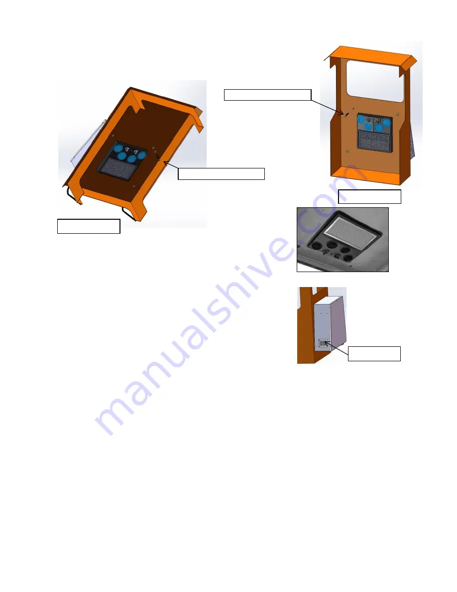
On units that have the optional heater attach hoses to the unit as shown below.  Secure heater hoses 
along the refrigerant hoses. 

4.


Route drain tubes over top of cab secure with clamps or tie-wraps.  Be sure drain hoses are at no point 
higher than where they leave the air conditioner.  Do not let condensate drip on stairs or walkways where 
it could cause a slip hazard. 


ROOF MOUNT 

WALL MOUNT 

(4) 3/8”- 16 x 1 ½” BOLT & WASHERS 

(4) 3/8”- 16 x 1 ½” BOLT & WASHERS 

16-40-1108K 

Summary of Contents for 4030 SERIES

Page 1: ...h side The air distribution plenum is attached and pre wired 2 Use the TEMPLATE provided to choose mounting location Avoid a location that requires cutting any of the roof stiffeners or any wall stiffeners If stiffeners are cut additional reinforcements may be required Do not cut or drill ROPS FOPS components block exits or obstruct the equipment operator s view 3 Mount the unit level or with the ...

Page 2: ...to the compressor ensure that the hoses will not bind or kink in any possible cab position Secure hoses so they will not chafe or become damaged Hoses must not come in contact with hot vehicle components exhaust manifolds etc Check to insure hoses will not be subject to mechanical abrasions 2 A 12 suction hose is recommended for hoses over 10ft 3 On units that have the optional heater attach hoses...

Page 3: ... wire to a power source with min 35amp breaker 12V or 20 amp breaker 24V We recommend a 10ga wire from source to the unit 4 Blue wire Connect to AUXILARY POWER CONDENSER or if using a RADIATOR MOUNTED CONDENSER connect to compressor clutch CAUTION BE SURE THERE IS HI LOW PRESSURE SWITCH INLINE BETWEEN THE EVAPORATOR AND THE COMPRESSOR HEATER HOSE LOCATE FITTINGS 2 EA 10 O RING STRAIGHT 5 8 dia HEA...

Page 4: ...ower switch to high speed and clutch rocker switch to on position clutch switch will light up when in the correct position a The a c clutch will be engaged b The evaporator blower will be on high speed c The condenser fan will be turning 6 Turn the fan switch to medium and low positions and evaporator motor should slow down 7 Turn the switch to the off position All motors and clutch will turn off ...

Reviews: