2
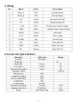
5. Wiring
No.
Marks
Color
Description
1
BELL_A
Pink
Doorbell button
2
BELL_B
Pink
Doorbell button
3
D0
Green
Wiegand output D0
4
D1
White
Wiegand output D1
5
+12V
Red
Positive pole of power supply
6
GND
Black
Negative pole of power supply
7
OPEN
Yellow
Exit button
8
D_IN
Brown
Door contact
9
ALARM
Gray
Alarm Output
10
NO
Blue
Relay NO end
11
COM
Purple
Relay Com end
12
NC
Orange
Relay NC end
6. Sound and Light Indication
Operation
LED Color
Buzzer
Standby
Red flash
Press key
Di
Read card
Green
Di-
Door Open
Green
Di-
Operation Successful
Green
Di-
Operation Failed
Di Di Di
PIN Inputting
Red
Card&PIN Inputting
Red
Multi Card Reading
Red
Under Menu
Red
Under Setting
Orange
Manager Card Enter
Orange
Di Di
Manager Card Exit
Red Flash
Di-
Alarm
Red Quick Flash
Alarm


