Fingerprint Access Control Terminal User Manual
9
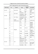
Cable Group
No.
Function
Color
Terminal
Name
Description
D6
Yellow/Grey
BUTTON
Exit Door
Wiring
D7
Doorbell
White/Brown BELL+
Doorbell
Wiring
D8
White/Blue
BELL-
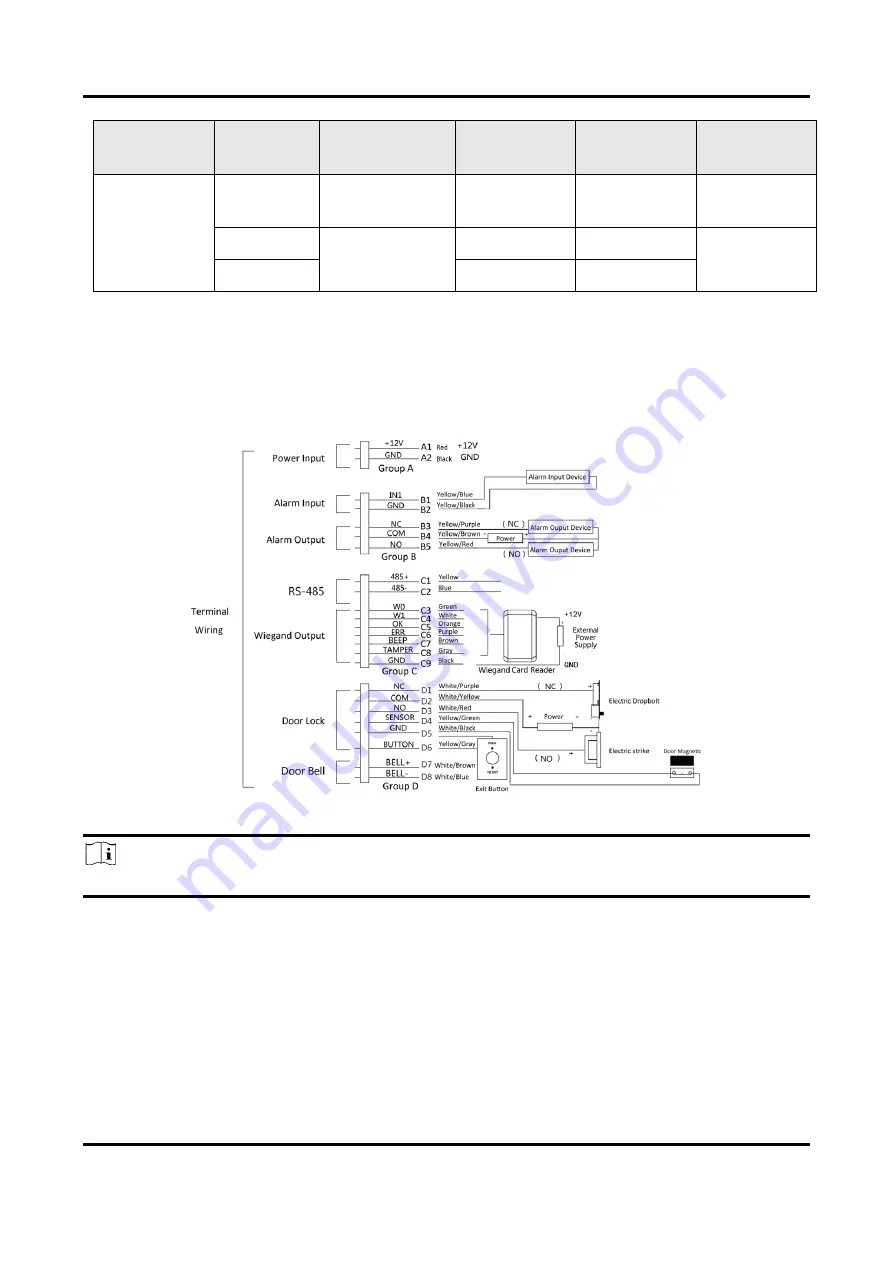
4.2 External Device Wiring
Wire the external device.
The wiring diagram is as follows.
Figure 4-2 External Device Wiring
Note
The external power supply and the access control terminal should use the same GND cable.
4.3 Secure Door Control Unit Wiring
The wiring diagram is as follows:
Summary of Contents for VIS-3013
Page 2: ......
Page 21: ...Fingerprint Access Control Terminal User Manual 7 Figure 4 1 Terminal Diagram...
Page 156: ......


