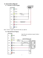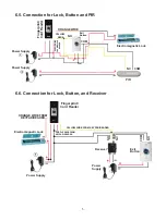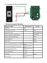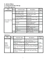
5. Wiring
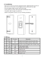
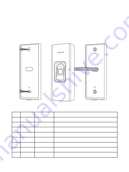
4. Installation
No. Color Function Description
1 Green D0 Wiegand input (Wiegand output as reader mode)
2 White D1 Wiegand input (Wiegand output as reader mode)
3 Yellow OPEN/ BEEP Exit button input end (Beeper input as reader mode)
4 Red +12V Positive power supply
5 Black GND Negative power supply
6 Blue NO Relay NO end
7 Purple COM Relay COM end
8 Orange NC Relay NC end
- Remove the back cover from the keypad using the supplied special screw driver
- Drill 2 holes on the wall for the self-tapping screws and hole for the cable
- Put the supplied rubber bungs to into the two holes
- Fix the back cover firmly on the wall with 2 self tapping screws
- Thread the cable through the cable hole
- Attach the keypad to the back cover. (as following illustration)
2

