background image


Copyright © 2010 

Part number 

400613-1


Printed in U.S.A. 

Authorized EU representative: Vislink PLC 

Quality Certification 

Vislink is certified to ISO 9001:2008. 

The Vislink trademark and other trademarks are registered trademarks in the United States and/or other countries. 

Microsoft®, Windows®, and Internet Explorer® are registered trademarks of Microsoft Corporation in the United States 
and/or other countries. 

Proprietary Material  

The information and design contained within this manual was originated by and is the property 

of Vislink. Vislink reserves all patent proprietary design, manufacturing, reproduction use, and sales rights thereto, and 
to any articles disclosed therein, except to the extent rights are expressly granted to others. The foregoing does not 
apply to vendor proprietary parts. Vislink has made every effort to ensure the accuracy of the material contained in this 
manual at the time of printing. As specifications, equipment, and this manual are subject to change without notice, 
Vislink assumes no responsibility or liability whatsoever for any errors or inaccuracies that may appear in this manual 
or for any decisions based on its use. This manual is supplied for information purposes only and should not be 
construed as a commitment by Vislink. The information in this manual remains the property of Vislink and may not be 
used, disclosed, or reproduced in any form whatsoever, without the prior written consent of Vislink. Vislink reserves the 
right to make changes to equipment and specifications of the product described in this manual at any time without 
notice and without obligation to notify any person of such changes. 

General Safety Information  

The following safety requirements, as well as local site requirements and regulations, 

must be observed by personnel operating and maintaining the equipment covered by this manual to ensure awareness 
of potential hazards. This equipment has been tested and found to comply with the limits for a Class A digital device, 
pursuant to Part 15 of the FCC Rules. These limits are designed to provide reasonable protection against harmful 
interference when the equipment is operated in a commercial environment. This equipment generates, uses, and can 
radiate radio frequency energy. If not installed and used in accordance with the instruction manual, it may cause 
harmful interference to radio communications. Operation of this equipment in a residential area is likely to cause 
harmful interference in which case the user will be required to correct the interference at his own expense. 

About this Manual  

This manual is intended for use by qualified operators, installers, and service personnel. Users of 

this manual should already be familiar with basic concepts of radio, video, and audio. For information about terms in 
this manual, see 

Glossary of Terms and Abbreviations 

(Part No. 400576-1). Pay special attention to Notes, Cautions, 

and Warnings. 

Read 

Notes 

for important information to assist you in using and maintaining the equipment. 

Follow 

CAUTIONS 

to prevent damage to the equipment. 

Follow 

WARNINGS 

to prevent personal injury or death. 
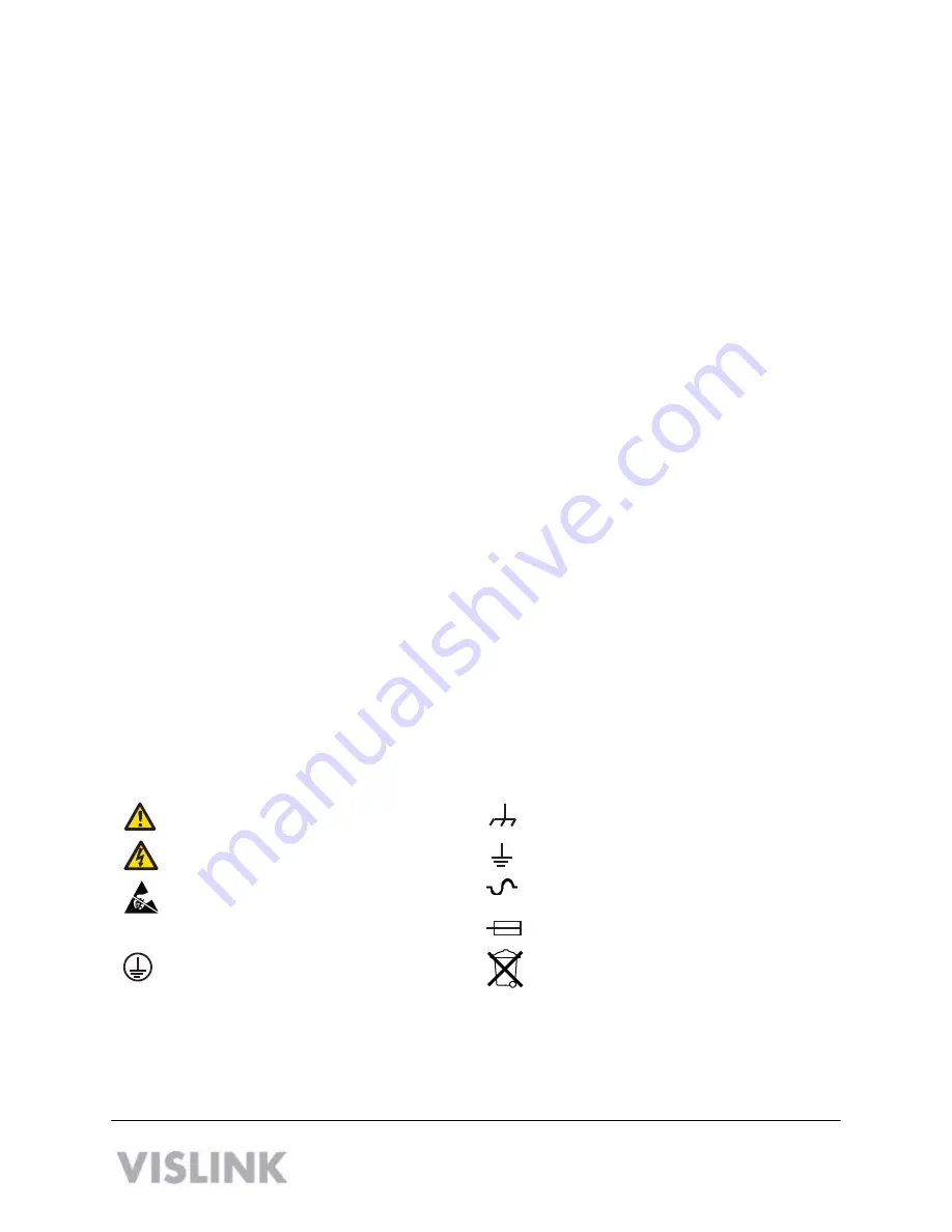
Symbols  

The following symbols may be on the equipment or in this manual: 

WARNING: General Warning. 
Risk of Danger. 

Frame or Chassis Ground: Identifies the frame 
or chassis terminal. 

WARNING: Risk of Electric Shock. 

Earth Ground: Identifies the earth ground 

terminal. 

CAUTION: Electrostatic Discharge. 


Possible Damage to Equipment. 

Fuse (either icon): 

Identifies fuses or their location. 


Protective Earth Ground: Identifies any 
terminal intended for connection to an 
external conductor for protection against elec- 
tric shock in case of a fault, or the 
terminal on a protective earth electrode. 

Waste Electrical and Electronic Equipment 
(WEEE): The product must not be disposed of 
with other waste. You must dispose of the 
waste equipment by handing it over to a desig- 
nated collection point for recycling. 


101 Billerica Avenue - Bldg. 6


North Billerica, MA 01862-1256 USA 

TEL:  800.490.5700 or +1.978.671.5700


Summary of Contents for HDX-1100C1

Page 1: ...HDX 1100 Aircraft Terrestrial High Power HD Video Transmitter User and Technical Manual Manual Part No 400613 1 Rev 2 March 2010 ...

Page 2: ...s This equipment has been tested and found to comply with the limits for a Class A digital device pursuant to Part 15 of the FCC Rules These limits are designed to provide reasonable protection against harmful interference when the equipment is operated in a commercial environment This equipment generates uses and can radiate radio frequency energy If not installed and used in accordance with the ...

Page 3: ...te control unit RCU see Section 4 You also can configure the HDX 1100 with a PC using a web browser see Section 5 2 Operating in Safety Guidelines for safe operation are derived from OET bulletin 65 August 1997 as recommended by the Federal Communications Commission FCC WARNING High levels of RF power are present in the unit Exposure to RF or microwave power can cause burns and may be harmful to h...

Page 4: ... cm milliwatts per square centimeters Conversions dBi to numeric gain Antilog dBi 10 Feet to centimeters Feet 30 48 Centimeters to Feet cm 0328 4 π 12 57 User Input RF power delivered to the antenna Watts Antenna gain referenced to isotropic antenna dBi Distance from the center of radiation Feet Calculation steps 1 P RF power input Watts to milliwatts Watts 1000 2 G Antenna gain dBi Numeric gain A...

Page 5: ...The touch panel screen on the front of the unit lets you control the HDX 1100 directly as described in the following sections 3 1 Selecting a Preset The HDX 1000 recalls the most recently saved preset when it is powered up You can select from up to 16 factory or custom preset configurations To select a preset do the following 1 Press the PRESET key 2 Press the up and down arrows to choose the new ...

Page 6: ...ng figure shows the RCU Function Name Description Push Buttons RF PWR Turns the unit on and off BRIGHTNESS Sets the display brightness to high H low L or automatic A light sensing LED Displays STBY Indicates the HDX 1100 is in standby mode not transmitting XMIT Indicates the HDX 1100 is in transmit mode DC OK Indicates DC Power is applied to the Remote Control Panel and transmitting FAULT Indicate...

Page 7: ...ommunication error has occurred If this happens check the power and serial cable connections 5 Setting the HDX 1100 with a PC To set up your HDX 1100 with a PC do the following 1 Connect a LAN cable to the network connection of a router or switch and the ethernet port on the HDX 1100 2 Open a web browser and type 192 168 4 150 into the URL address field and press Enter To configure the parameters ...

Page 8: ...ppears 4 Configure the video and audio parameters as required for the preset and click Apply 5 Select RF Settings from the Radio drop down menu The RF Band Settings screen appears 6 Configure the video and audio parameters as required for the preset and click Apply 6 HDX 1100 User and Technical Manual ...

Page 9: ...e preset and click Apply 9 Select Encryption Settings from the Radio drop down menu The Encryption Settings screen appears 10 Configure the video and audio parameters as required for the preset and click Apply Note For 128 bit encryption enter 32 hexadecimal characters For 256 bit encryption enter 64 hexadecimal characters HDX 1100 User and Technical Manual 7 ...

Page 10: ...u The Presets screen appears 14 Configure the video and audio parameters as required for the preset and click Store 5 1 Recalling a Preset Configuration from a PC 1 Select Preset from the Radio drop down menu 2 Select the preset number and click Load The relevant parameters will be populated under Video and Radio Note The Encryption code will not display Click Logout to finish setting up the HDX 1...

Page 11: ...ng frequency bands Model Band Frequency Power Consumption Frequency Stability Frequency Step Size HDX 1100LS LS 1 7 2 5 GHz 44W 2 5 ppm 250 Khz HDX 1100S S 2 4 2 48 GHz 44W 2 5 ppm 250 Khz HDX 1100C1 C1 3 1 3 5 GHz 46W 2 5 ppm 250 Khz HDX 1100C2 C2 4 4 5 0 GHz 46W 2 5 ppm 250 Khz HDX 1100C3 C3 6 4 7 2 GHz 46W 2 5 ppm 250 Khz HDX 1100X X 8 1 8 5 GHz 48W 2 5 ppm 250 Khz 6 2 Video Input Connectors Th...

Page 12: ...ired by the equipment I O connector 26 Pin Male D connector pin outs are shown in the following table Connector Pin Description Pin Description A Vin P Serial CTRL Out B Vin R N C C N C S N C D Audio 1 In T Reserved E GND U Reserved F GND V Reserved G Audio 2 In W Reserved H N C X Reserved J Data Channel In Y Reserved K GND Z Reserved L N C a Reserved M Serial CTRL In b Vin N Serial CTRL GND c Vin...

Page 13: ...th VSWR 1 5 1 Protection Transmitters shall not be damaged by an infinite VSWR at any phase angle at the RF output ports for an indefinite time 6 8 Audio Characteristics Two audio inputs are to be supported which can be both line both microphone or one of each 6 9 Video Input Format ASI 188 byte EN50083 9 HD SDI SMPTE 292M 1920x1080i 25fps 1920x1080i 30fps 1280x720 50 fps 1280x720 60fps Composite ...

Page 14: ...nical Support include the following information Model number and serial number of the unit located on a label on the bottom of each unit Approximate purchase date There are no supported field repairs to the HDX 1100 Return the unit for factory repair CAUTION If you attempt field repair you risk damaging your equipment If your equipment is under warranty you may also affect your warranty coverage T...

Reviews: