


1
About the HDX-1100
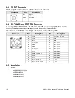
The
HDX-1100 Aircraft/Terrestrial High Power HD
Video Transmitter
(HDX-1100) (shown) is a
lightweight and rugged transmitter that is suited for
mobile and aircraft environments; able to withstand
constant vibration, shock, temperature swings, and
humidity. Common uses include law enforcement
surveillance and video collection.
The HDX-1100 supports H.264/MPEG-2 and
HD/SD. The HDX-1100 can transmit DVB-T
COFDM digital transmission (QPSK, 16QAM,
64QAM) consisting of a standard definition
(SD) NTSC or PAL video signals or high-
definition (HD) video signal (up to 1080i), plus
two audio signals and an RS-232 data
channel. The transmitter uses the MPEG-2
video compression format for high-quality
imagery.
The amplifier operates at 8W for all bands except 4940-4990 MHz which is limited to 1.0W
maximum. Low power mode is typically 3 to 6 dB below the maximum rating.
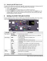
You can control the HDX-1100 with the touch screen user interface (see
Section 3
), or an
optional remote control unit (RCU) (see
Section 4
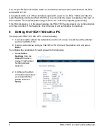
). You also can configure the HDX-1100 with a
PC using a web browser (see
Section 5
).
2
Operating in Safety
Guidelines for safe operation are derived from OET bulletin 65, August 1997, as recommended
by the Federal Communications Commission (FCC).
WARNING
High levels of RF power are present in the unit. Exposure to RF or
microwave power can cause burns and may be harmful to health.
Remove power from the unit before disconnecting any RF cables and
before inspecting damaged cables and/or antennas. Avoid standing in
front of high gain antennas (such as a dish antenna) and never look into
the open end of a waveguide or cable where RF power may be present.
The HDX-1100, operated without an antenna, will not create RF energy exceeding 1.0 mW/cm
2
,
the FCC limit for exposure. Connecting an antenna to the unit greatly enhances the potential for
harmful exposure, and you must maintain a certain distance from the radiator. The following
table shows the Maximum Permissible Exposure (MPE) safe distances from the antenna.
Antenna Gain (dB1)
0
2
3
5
11
Safe Distance (cm)
4
6
6
8
15
Safe Distance (in)
1.57
2.36
2.36
3.15
5.9
HDX-1100 User and Technical Manual
1


