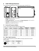
background image

P

o

w

e

D

e

n

s

it

y

 (

m

W

/c

m

^

2

)


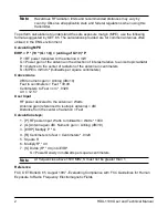
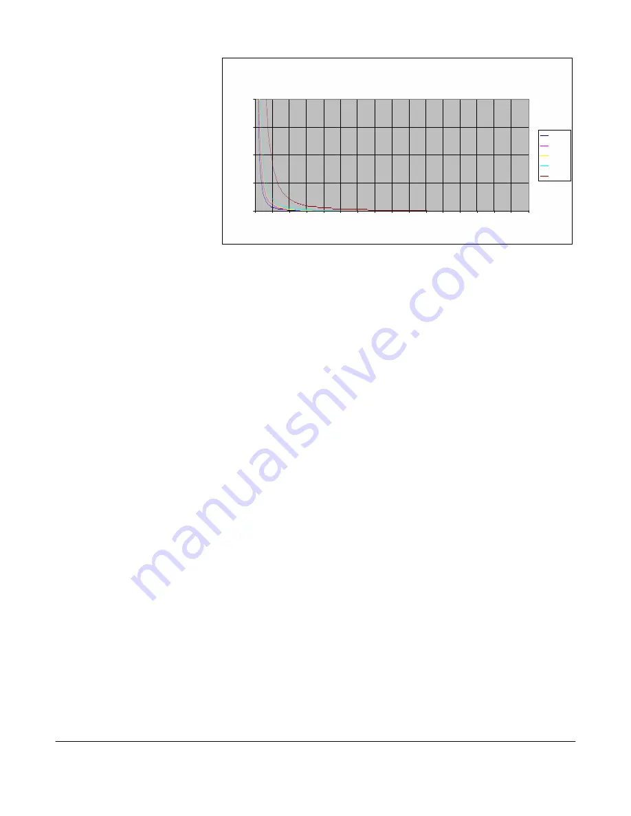
The figure to the right is a 
typical graph for a Vislink 
HDX-1100 Transmitter and 
shows the permissible 
exposure distance for 
various antennas. Graphs 
and data will vary, based on 
the actual transmitter, output 
power, frequency, and 
antenna utilized. One plot 
provides the permissible 
output of the transmitter for 
digital modulation, and the 
other plot for analog 
modulation. 


1.5 


0.5 


Maximum  Permissible Exposure


@  200 milliWatts RF Power


0       0.5     1     1.5     2     2.5     3     3.5      4     4 .5     5     5.5     6     6.5      7     7.5     

Distance in Feet


0dBi 

2dBi 

3dBi 

5dBi 

11dBi 


Vislink, in accordance with the requirements set forth by the FCC, provides this information as a 
guide to the user and assumes the users of this equipment are licensed and qualified to operate 
the equipment per the guidelines and recommendations contained within the product user 
guides and in accordance with any FCC rules that may apply. 


Setting the HDX-1100 With the Touch Panel


The touch panel screen on the front of the unit lets you control the HDX-1100 directly as 
described in the following sections. 


3.1  Selecting a Preset


The HDX-1000 recalls the most recently saved preset when it is powered up. You can select 
from up to 16 factory or custom preset configurations.To select a preset, do the following: 


1.   Press the 

PRESET 

key. 

2.   Press the up and down arrows to choose the new preset you want. 

3.   Press the 

SAVE 

key. If the 

SAVE 

key is not pressed within 5 seconds, the preset returns 

to the most recently used value and the selection mode is canceled. 


3.2  Selecting the Audio Input Level


The HDX-1100 recalls the most recently saved audio input level setting when it is powered up. 
To select the input level for Audio 1 and Audio 2 between microphone or line level, do the 
following: 


1.   Press the 

AUDIO 1 MIC/LINE 

or 

AUDIO 2 MIC/LINE 

key. 

2.   Press 

AUDIO 1 MIC/LINE 

or 

AUDIO 2 MIC/LINE 

key to toggle between MIC or LINE 

level. 

3.   Press the 

SAVE 

key.If the 

SAVE 

key is not pressed within 5 seconds, the audio level 

returns to the most recently used value and the selection mode is canceled. 


HDX-1100 User and Technical Manual 

Summary of Contents for HDX-1100C1

Page 1: ...HDX 1100 Aircraft Terrestrial High Power HD Video Transmitter User and Technical Manual Manual Part No 400613 1 Rev 2 March 2010 ...

Page 2: ...s This equipment has been tested and found to comply with the limits for a Class A digital device pursuant to Part 15 of the FCC Rules These limits are designed to provide reasonable protection against harmful interference when the equipment is operated in a commercial environment This equipment generates uses and can radiate radio frequency energy If not installed and used in accordance with the ...

Page 3: ...te control unit RCU see Section 4 You also can configure the HDX 1100 with a PC using a web browser see Section 5 2 Operating in Safety Guidelines for safe operation are derived from OET bulletin 65 August 1997 as recommended by the Federal Communications Commission FCC WARNING High levels of RF power are present in the unit Exposure to RF or microwave power can cause burns and may be harmful to h...

Page 4: ... cm milliwatts per square centimeters Conversions dBi to numeric gain Antilog dBi 10 Feet to centimeters Feet 30 48 Centimeters to Feet cm 0328 4 π 12 57 User Input RF power delivered to the antenna Watts Antenna gain referenced to isotropic antenna dBi Distance from the center of radiation Feet Calculation steps 1 P RF power input Watts to milliwatts Watts 1000 2 G Antenna gain dBi Numeric gain A...

Page 5: ...The touch panel screen on the front of the unit lets you control the HDX 1100 directly as described in the following sections 3 1 Selecting a Preset The HDX 1000 recalls the most recently saved preset when it is powered up You can select from up to 16 factory or custom preset configurations To select a preset do the following 1 Press the PRESET key 2 Press the up and down arrows to choose the new ...

Page 6: ...ng figure shows the RCU Function Name Description Push Buttons RF PWR Turns the unit on and off BRIGHTNESS Sets the display brightness to high H low L or automatic A light sensing LED Displays STBY Indicates the HDX 1100 is in standby mode not transmitting XMIT Indicates the HDX 1100 is in transmit mode DC OK Indicates DC Power is applied to the Remote Control Panel and transmitting FAULT Indicate...

Page 7: ...ommunication error has occurred If this happens check the power and serial cable connections 5 Setting the HDX 1100 with a PC To set up your HDX 1100 with a PC do the following 1 Connect a LAN cable to the network connection of a router or switch and the ethernet port on the HDX 1100 2 Open a web browser and type 192 168 4 150 into the URL address field and press Enter To configure the parameters ...

Page 8: ...ppears 4 Configure the video and audio parameters as required for the preset and click Apply 5 Select RF Settings from the Radio drop down menu The RF Band Settings screen appears 6 Configure the video and audio parameters as required for the preset and click Apply 6 HDX 1100 User and Technical Manual ...

Page 9: ...e preset and click Apply 9 Select Encryption Settings from the Radio drop down menu The Encryption Settings screen appears 10 Configure the video and audio parameters as required for the preset and click Apply Note For 128 bit encryption enter 32 hexadecimal characters For 256 bit encryption enter 64 hexadecimal characters HDX 1100 User and Technical Manual 7 ...

Page 10: ...u The Presets screen appears 14 Configure the video and audio parameters as required for the preset and click Store 5 1 Recalling a Preset Configuration from a PC 1 Select Preset from the Radio drop down menu 2 Select the preset number and click Load The relevant parameters will be populated under Video and Radio Note The Encryption code will not display Click Logout to finish setting up the HDX 1...

Page 11: ...ng frequency bands Model Band Frequency Power Consumption Frequency Stability Frequency Step Size HDX 1100LS LS 1 7 2 5 GHz 44W 2 5 ppm 250 Khz HDX 1100S S 2 4 2 48 GHz 44W 2 5 ppm 250 Khz HDX 1100C1 C1 3 1 3 5 GHz 46W 2 5 ppm 250 Khz HDX 1100C2 C2 4 4 5 0 GHz 46W 2 5 ppm 250 Khz HDX 1100C3 C3 6 4 7 2 GHz 46W 2 5 ppm 250 Khz HDX 1100X X 8 1 8 5 GHz 48W 2 5 ppm 250 Khz 6 2 Video Input Connectors Th...

Page 12: ...ired by the equipment I O connector 26 Pin Male D connector pin outs are shown in the following table Connector Pin Description Pin Description A Vin P Serial CTRL Out B Vin R N C C N C S N C D Audio 1 In T Reserved E GND U Reserved F GND V Reserved G Audio 2 In W Reserved H N C X Reserved J Data Channel In Y Reserved K GND Z Reserved L N C a Reserved M Serial CTRL In b Vin N Serial CTRL GND c Vin...

Page 13: ...th VSWR 1 5 1 Protection Transmitters shall not be damaged by an infinite VSWR at any phase angle at the RF output ports for an indefinite time 6 8 Audio Characteristics Two audio inputs are to be supported which can be both line both microphone or one of each 6 9 Video Input Format ASI 188 byte EN50083 9 HD SDI SMPTE 292M 1920x1080i 25fps 1920x1080i 30fps 1280x720 50 fps 1280x720 60fps Composite ...

Page 14: ...nical Support include the following information Model number and serial number of the unit located on a label on the bottom of each unit Approximate purchase date There are no supported field repairs to the HDX 1100 Return the unit for factory repair CAUTION If you attempt field repair you risk damaging your equipment If your equipment is under warranty you may also affect your warranty coverage T...

Reviews: