Docu
6
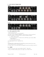
L21
L20
L21
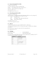
6.1
75
Ω
(if o
Note
Dem
For c
Note
Thes
limit
In Tr
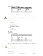
6.2
75
Ω
ASI i
ument: CL140
I
NPUT
/
O
174
074
170
RF1-4 in
BNC type cha
only 2 inputs lic
e:- When oper
modulator settin
•
UHF inp
•
Receiver
@DVB-T
•
Max inpu
configuration p
e:-
se inputs can h
ed to 400mA p
riax mode, inp
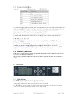
ASI IN
BNC chassis
input to the D
0072
O
UTPUT
C
O
puts (L217
assis connecto
censed, inputs
ating in 20MH
ngs for 1 & 2
ut 70MHz to 8
performance m
T QPSK 1/2)
ut (damage leve
please refer to
have +20VDC
per connector
puts 1 & 2 are
mounted sock
Decoder, Packe
L2
ONNECTION
4, L2074)
or
3 & 4 are non
Hz LMS-T
RF
should also be
860MHz.
meets or excee
el): 2W (CW)
o 9.1 Demodul
output (set in
, short circuit p
used in Single
ket. Complies w
et diversity blo
2174 Manual Is
NS
n-operational)
1 & 2
are used
e used to confi
eds ES 202 239
lator Menu
n Unit/LNB P
protected.
mode; in Dua
with ISO/IEC
ock, ASI outpu
ssue 2.0
d for connecti
igure the appro
9 in DVB-T m
ower) to powe
al mode the se
C 13818-2 – 18
ut connector, o
on to the two
opriate RF inp
mode (typical se
er the external
cond system is
88byte mode.
or Video-IP blo
Pag
down convert
puts.
ensitivity -93d
down convert
s added to inp
ock.
ge 9 of 26
tors.
dBm
ter;
uts 3 & 4.


