background image

4-2   Troubleshooting

PTX-PRO User and Technical Manual

The mounting hardware for the 

PTX-PRO

 is listed in the following table.

4.1.2

Supported Repairs

There are no supported field repairs to the PTX-PRO. Return the unit for factory repair. 

CAUTION

If you attempt field repair, you risk damaging your equipment. 

If 

your equipment is under warranty, you may also affect your warranty 
coverage. The PTX-PRO requires specialized test equipment and 
software to calibrate operating characteristics after repair. 

4.2 Addressing General Problems

Part

Description

Antenna Lock Plate

Attaches an MRC antenna directly to PTX-PRO RF output connector.

Quick Release

Provides quick release mounting of the PTX-PRO on an MRC tripod

Problem

Possible Cause

Action

PWR

 LED on

PTX-PRO is off 
when 

PWR

 switch is 

set to on ( 

I

 ).

Missing input power.

Make sure power cable is connected properly.

Make sure power source on.

Check input power voltage.

Check both 

AC

 and 

DC

 power fuses.

PWR

 LED on 

PTX-PRO is amber.

PTX-PRO is 
indicating a 

Minor 

Alarm

.

Check all Monitor Screens on PTX-PRO display. 
See 

Section 4.3, 

Addressing Display Error 

Messages

 on page 4-3.

Check Error Code Screen on PTX-PRO display. 
See 

Section 4.4, 

Addressing Video Problems

 on 

page 4-3.

PWR

 LED on 

PTX-PRO is red.

PTX-PRO is 
indicating a 

Major 

Alarm

.

TURN OFF POWER and call for service.

Test Tone is on and 
cannot be turned off 
from the radio.

Audio must be set 
from the Configurator 
(and cannot be set 
from the radio). 
Configurator setup is 
incorrect. 

Before programming the radio from the 
configurator, click 

Load all Settings

, which will 

set the audio automatically from the radio. See 

Section 3.5, 

Configuring the PTX-PRO With a PC


on page 3-4

Set 

Audio Input

 to 

Analog

SDI EMB

, or 

AES 

EBU

, or set 

Audio Type

 to

 OFF

. See 

MPEG Tab 

on page 3-7.

Summary of Contents for PTX-PRO

Page 1: ...PTX PRO Transmitter User and Technical Manual Part No 400611 1 Rev D January 2012 ...

Page 2: ...s This equipment has been tested and found to comply with the limits for a Class A digital device pursuant to Part 15 of the FCC Rules These limits are designed to provide reasonable protection against harmful interference when the equipment is operated in a commercial environment This equipment generates uses and can radiate radio frequency energy If not installed and used in accordance with the ...

Page 3: ...stalling Configurator Software 2 8 3 Operating the PTX PRO 3 1 Powering Up 3 1 3 2 Using the Display Screen 3 1 3 3 Monitoring PTX PRO Operations 3 2 3 4 Configuring the PTX PRO Manually 3 3 3 5 Configuring the PTX PRO With a PC 3 4 3 5 1 Connecting the PTX PRO to the MRC Radio Configurator 3 4 3 5 2 Loading Parameters from the Radio or a File 3 5 3 5 3 Saving Parameters to the Radio or a File 3 5...

Page 4: ...r Connections A 1 A 2 1 Power Supply and Distribution A 1 A 3 Audio Connections A 3 A 3 1 Front Panel Audio Connections A 3 A 3 2 Rear Panel Audio Connections A 4 A 3 3 MPEG Audio input A 5 A 3 4 AES EBU Audio input A 5 A 4 Video Connections A 5 A 5 Data Connections A 5 A 5 1 Wayside Data A 7 A 5 2 Networking A 7 Index ...

Page 5: ...d Outside Broadcast OB systems The RF frequency synthesizer circuit included in the IF RF module in conjunction with the command and control power supply module creates RF video and audio signal channels in the various standard FCC band plans You can use standard U S FCC band plans or create custom channel plans using the MRC Radio Configurator software on a PC The PTX PRO includes MPEG CODFM modu...

Page 6: ...selected channel displays on the Main screen See Section 1 4 Channel Plans 2 7 and 13 on page 1 5 for information about channel plans OFFSET Switch Lets you set the channel offset 0 or channel offset Note For the 13 GHz plan you cannot select offset minus for Channel 1 and you cannot select offset plus for Channel 22 Dual Band Switch On PRX PRO dual band models only lets you set the channel to 2 G...

Page 7: ...ally on page 3 3 Press the control switch to set a parameter or lock a display while it continues to update press it again to unlock it ASI INPUT 75 Ohm BNC Female Connector Provides ASI inputs to the unit SDI HD SD 75 Ohm BNC Female Connector Provides the HD SD SDI data stream input to the unit MONITOR 75 Ohm BNC Female Connector Provides 70 MHz output for external signal monitoring SIGNAL INPUT ...

Page 8: ... with AC power sources DC Fuse Provides DC input power protection for units used with DC power sources CAUTION Avoid possible equipment damage If you are using a DC power source for your PTX PRO do not exceed 36 volts DC input power RS 232 DB 9 Connector Provides a connection to a Windows based PC when using the Configurator software or connection for Wayside data 1 3 Related Documents Glossary of...

Page 9: ...076 500 2079 500 2082 500 6 2088 500 2091 500 2094 500 7 2100 500 2103 500 2106 500 8 2454 250 2458 500 2462 750 9 2471 000 2475 250 2479 500 10 2487 500 2491 750 2496 000 Channel Offset MHz 0 Center MHz Offset MHz 1 6881 250 6887 500 6893 750 2 6906 250 6912 500 6918 750 3 6931 250 6937 500 6943 750 4 6956 250 6962 500 6968 750 5 6981 250 6987 500 6993 750 6 7006 250 7012 500 7018 750 7 7031 250 ...

Page 10: ... 250 7005 000 7020 750 4 7035 250 7050 000 7065 750 5 7080 250 7095 000 7110 750 6 7125 250 7140 000 7155 750 7 7170 250 7185 000 7200 750 8 7215 250 7230 000 7245 750 9 7260 250 7275 000 7290 750 10 7305 250 7320 000 7335 750 11 7350 250 7365 000 7380 750 12 7395 250 7410 000 7425 750 13 7440 250 7455 000 7470 750 14 7485 250 7500 000 7500 000 1 6 About the PTX PRO PTX PRO User and Technical Manu...

Page 11: ...868 750 8 12881 250 12887 500 12893 750 9 12906 250 12912 500 12918 750 10 12931 250 12937 500 12943 750 11 12956 250 12962 500 12968 750 12 12981 250 12987 500 12993 750 13 13006 250 13012 500 13018 750 14 13031 250 13037 500 13043 750 15 13056 250 13062 500 13068 750 16 13081 250 13087 500 13093 750 17 13106 250 13112 500 13118 750 18 13131 250 13137 500 13143 750 19 13156 250 13162 500 13168 75...

Page 12: ...les connectors switches and displays to ensure that they are not broken damaged or loose If you discover damage after unpacking the system report the damage as follows Immediately file a claim with the shipping carrier Forward a copy of the damage report to Vislink Customer Service Contact Vislink Customer Service to determine the disposition of the equipment See Section 4 1 Getting Support for Yo...

Page 13: ...2 the FCC limit for exposure Once connected to an antenna the potential for harmful exposure will be greatly enhanced In this situation a certain distance from the radiator is to be maintained Calculations need to be performed to understand what that safe margin for exposure is This is known as the Maximum Permissible Exposure MPE limit Calculations provided are for common antennas often utilized ...

Page 14: ...Exposure to Radio Frequency Electromagnetic Fields The following graph and associated table show the permissible exposure distance for various antennas Graphs and data will vary based on the actual transmitter output power frequency and antenna utilized One plot provides the permissible output of the transmitter for digital modulation and the other plot for analog modulation This information is pr...

Page 15: ...odify a grounded power plug to connect to an ungrounded receptacle Ensure that the power being supplied matches the power required by the equipment You can find power ratings for equipment on a rating plate usually on the rear panel Ensure that the electrical supply is protected by over current protection devices as required by the applicable electrical codes If necessary consult a licensed electr...

Page 16: ... Plate machined into the MRC tripod mount The versatility of the Quick Release Mount and a mating Dovetail Adapter Plate let you attach the Dovetail Adapter Plate to the bottom of the PTX PRO and the Quick Release Mount to a non MRC tripod or vice versa 2 4 Mounting on a Non MRC Tripod Option 1 To mount a PTX PRO on a non MRC tripod attach the Quick Release Mount to the bottom of the PTX PRO using...

Page 17: ...TX PRO to a non MRC tripod that contains a QuickSet tripod mount This option requires the use of a QuickSet Quick Change Adapter The Quick Change Adapter is attached to the bottom of the PTX PRO using four 1 2 inch long 6 32 pan head screws lock washers and flat washers The Quick Change Adapter and PTX PRO assembly is then attached to the QuickSet tripod mount and is secured with the tripod mount ...

Page 18: ...od the antenna typically is attached to the Antenna Lock Plate mounted on the PTX PRO as shown in the following figure An optional Rain Shield is also available for portable applications in inclement weather Antenna 2 options shown Antenna Lock Plate PTX PRO Receiver Quick Release Mount Tripod Optional Rain Shield ...

Page 19: ...B of free hard disk space CD ROM drive Internet Explorer 4 01 SP1 or later One RS 232 I O port configured as COM 1 thru COM 9 To install the Configurator insert the product CD and follow the instructions on the Setup Wizard Upon successful installation the MRC Radio Configurator icon displays on your desktop Note If you already have a version of the MRC Radio Configurator installed you must uninst...

Page 20: ...mitting and receiving video and audio If the PTX PRO does not power up normally see Chapter 4 Troubleshooting 3 2 Using the Display Screen The screen on the PTX PRO transmitter displays the values of the selected preset and the output power For example Preset 1 0 00W C 1 The Control switch lets you monitor status and set functions displayed on the PTX PRO screen The Control Switch cycles through i...

Page 21: ... sequences of each mode Monitor Menu Sequence Clockwise Analog IF ASI In CODFM Mode EXT IF Mode LMS T Mode 12712 500MHz 0 00W C 1 12712 500MHz 0 00W C 1 12712 500MHz 0 00W C 1 12712 500MHz 0 00W C 1 12712 500MHz 0 00W C 1 TX Attn 0 0db TX Attn 0 0db TX Attn 0 0db TX Attn 0 0db TX Attn 0 0db Band 13 GHz Band 13 GHz Band 13 GHz Band 13 GHz Band 13 GHz Mode Analog IF Mode ASI SDI In Mode COFDM Mode E...

Page 22: ... VI Mode SD 1 Press the Control Switch the value flashes 2 Turn the Control Switch to select SD or HD 3 Press the Control switch to set the desired mode Change SD video input OR Chng SD VI NTSC 1 Press the Control Switch the value flashes 2 Turn the Control Switch to select NTSC or NTSC NoPdstl or 525 Line SDI 3 Press the Control switch to set the desired SD video input Change HD video input Chng ...

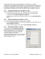
Page 23: ... interrupt broadcast operations Do not place the PTX PRO in transmit mode when using the MRC Radio Configurator Also the PTX PRO must be powered up before you run the MRC Radio Configurator For information about installing the MRC Radio Configurator see Section 2 5 Installing Configurator Software on page 2 8 3 5 1 Connecting the PTX PRO to the MRC Radio Configurator On the Main tab of the MRC Rad...

Page 24: ... the PTX PRO into the MRC Radio Configurator click the Load All Settings from Radio box To load parameter settings from a previously saved file click the Load All Settings from File box 3 5 3 Saving Parameters to the Radio or a File You can save the parameter settings to the radio or a file as follows To save parameter settings from the MRC Radio Configurator to the PTX PRO click the Save All Sett...

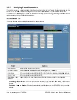
Page 25: ...ons Radio Mode Tab You can set the radio mode parameters for each preset Load Page from Radio To load parameters for this page from the PTX PRO click on this button Program Page to Radio To apply parameter modifications to the PTX PRO click on this button Field Options Preset Name Displays the name of the preset Operation Mode Select CODFM ASI IN Ext IF In Analog IF out or LMS T Color Bars Where a...

Page 26: ...ork for this preset Input When Radio Type is NTSC and HD SD is SD you can choose SDI 525 In NTSC In NTSC Pedestal This field is inactive for HD When Radio Type is PAL and HD SD is SD you can choose SDI 625 In PAL In PAL M or PAL N This field is inactive for HD Chroma Choose 4 2 0 or 4 2 2 Delay When HD SD is SD you can choose Standard or Low This field is inactive for HD ASI Rate Specify a value f...

Page 27: ...reo or Dual Mono Input When Type is not OFF choose Test Tone Analog SDI EMB or AES EBU Note Test Tone is used only for audio testing and antenna alignment testing Auto align Dolby E When Type is Dolby E you can check this box Encryption Type Requires a license Select OFF BISS 1 or BISS E 1 Key If you selected BISS 1 then also specify the BISS 1 key value E Key If you selected BISS E then also spec...

Page 28: ... COFDM and ASI In operation modes Load Page from Radio To load parameters for this page from the PTX PRO click on this button Program Page to Radio To apply parameter modifications to the PTX PRO click on this button Field Option Preset Name Displays the name of the preset Modulation Type Select QPSK 16 QAM or 64 QAM Bandwidth Select 6 MHz 7 MHz or 8 MHz FEC Select 1 2 2 3 3 4 5 6 or 7 8 Guard Sel...

Page 29: ...eters Note Fields on the LMS T tab are active only for LMS T operation mode Load Page from Radio To load parameters for this page from the PTX PRO click on this button Program Page to Radio To apply parameter modifications to the PTX PRO click on this button Field Option Preset Name Displays the name of the preset Modulation Type Select QPSK or 16 QAM Bandwidth Select 10 MHz or 20 MHz FEC Select 2...

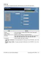
Page 30: ...to Radio To apply parameter modifications to the PTX PRO click on this button Field Options Presets Click on the preset to display the parameter values of that preset Video Deviation Choose 3 or 4 MHz Enable Channel 1 2 3 4 Enable to access additional channel specifications Frequency When the channel is enabled Choose one of the following frequencies 4830 5200 5800 6200 6800 7020 7500 8065 8300 85...

Page 31: ... Apply the parameter settings from the PTX PRO to the Channel Plan screen Program All Bands to Radio Apply the parameter settings to the PTX PRO Read Bands from File Click to select a previously saved file to load your channel plan Save Bands to File Save the settings to a file that you can load on this or other PTX PRO radios Field Option Offset Specify the MHz values from your channel plan or ac...

Page 32: ...Operating the PTX PRO 3 13 PTX PRO User and Technical Manual Load Default Values Click to load the default channel plan values Clear Values Click to clear all channel plan values ...

Page 33: ...ial Number Displays the serial number of your PTX PRO Firmware Number Displays the firmware number of your PTX PRO License Key Enter the license key obtained from Vislink Customer Service then click the Set Key button Set Key button Submits the licence key value if valid the corresponding license is enabled Licensed Features box Displays the features you can use with your PTX PRO To obtain additio...

Page 34: ...consult the factory Part Description AC Power Cable 120 VAC Connects AC power to the PTX PRO Connectors on both ends AC Power Cable 240 VAC Connects AC power to the PTX PRO Connectors on one end only DC Power Cable 11 0 to 36 0 VDC Connects DC power to the PTX PRO Connector on one end only Audio Input Cable Provides input to PTX PRO AUDIO 1 and 2 connectors from 2 XLR connectors See Section A 3 Au...

Page 35: ...h is set to on I Missing input power Make sure power cable is connected properly Make sure power source on Check input power voltage Check both AC and DC power fuses PWR LED on PTX PRO is amber PTX PRO is indicating a Minor Alarm Check all Monitor Screens on PTX PRO display See Section 4 3 Addressing Display Error Messages on page 4 3 Check Error Code Screen on PTX PRO display See Section 4 4 Addr...

Page 36: ... have suffered internal failure No Video The PTX PRO is unable to lock onto video signal Check for correct operation mode Check cable connections to SIGNAL INPUT and SDI ASI INPUT connectors Use Configurator software to check settings If message persists unit may have suffered internal failure Problem Possible Cause Action No video Problem with video source or cabling Check video source and cablin...

Page 37: ...Error Codes related to power E03A thru E03E Verify cable connectors are fully mated and verify cable and connectors are undamaged Make sure power cable is connected properly E031 5 5 Volt Reference Error E032 7 Volt Line Error E033 11 Volt Line Error E034 Temperature Error Check PTX PRO to be sure it is not too close to sources of heat Relocate PTX PRO if possible Verify PTX PRO has room around it...

Page 38: ...able Installed PTX PRO hardware is defective Contact Technical Support Configuration File Corrupt OR Unable to Open Configuration File Unable to read data stored in file chosen Select a different configuration file File damaged Re create configuration and save it with a different file name Problem with PC or its disk drive Contact your PC service provider Configurator won t install on PC Previous ...

Page 39: ...4 6 Troubleshooting PTX PRO User and Technical Manual ...

Page 40: ...s for equipment can be found on a rating plate usually on the rear panel If necessary consult a licensed electrician A 2 1 Power Supply and Distribution The PTX PRO PWR power connector is located on the front panel The mating connector that plugs into this panel connector is as follows Manufacturer ITT Cannon Part Number KPT06F14 12SX Manufacturer Amphenol Part Number PT06E14 12SX The following ta...

Page 41: ...r Cable Assemblies are available from MRC to connect the PTX PRO PWR connector to either 120 VAC or 240 VAC The AC Power Cable Assemblies are 6 0 ft 1 8 m long The 120 VAC Power Cable Assembly comes complete with power connectors on both ends The following figure shows the wiring diagram of the 120 VAC Power Cable Assembly The 240 VAC Power Cable Assembly comes with a power connector on one end on...

Page 42: ...the wiring diagram of the DC Power Cable Assembly A 3 Audio Connections The PTX PRO can provide analog or digital audio inputs All audio inputs are available at either the front or rear panel audio connectors A 3 1 Front Panel Audio Connections Front panel AUDIO 1 L1 and AUDIO 2 XLR R1 connectors are used for MPEG Audio A inputs or analog subcarriers 1 and 2 Connector pin outs are shown in the fol...

Page 43: ...ections into two separate cables with XLR connectors One cable assembly is included with each PTX PRO ordered Connector Information Pin Out Signal Description A DIGITAL 1 CH1 B DIGITAL 1 2 GND C DIGITAL 1 CH1 D DIGITAL 2 CH2 E DIGITAL 2 CH2 F ANALOG 3 LEFT CH2 G ANALOG 3 4 COM H ANALOG 3 LEFT CH2 J ANALOG 4 RIGHT CH2 K ANALOG 4 RIGHT CH2 A B C D E F G H J K RoHS 907471 1 REV F AV040910 2408 1 2 3 ...

Page 44: ...MPEG decoder to the AUDIO connector When configured for digital audio input AES EBU the MPEG decoder provides two paired channels of digital data and or four individual channels All four circuits are balanced inputs with each pair and sharing one ground A 4 Video Connections The PTX PRO provides several video options on the front panel using 75 Ohm BNC connectors as described in the following tabl...

Page 45: ...Data Communication Equipment DCE device connector that connects to a modem GPS etc When you connect the Multipurpose Data Cable to a WAYSIDE DB 9 female DCE device you also must connect a null modem between the DCE device and the WAYSIDE female connector If the WAYSIDE connector is connected to a DTE device you cannot use a null modem cable but you will need a straight pin to pin extension cable T...

Page 46: ... cable connects to the RS 232 connector on the PTX PRO and has connections for both the Wayside channel and the PC required for use with the MRC Radio Configurator software A 5 2 Networking You can connect the RS 232 connector on the PTX PRO to a network to monitor and program the PTX PRO from a remote location To connect the PTX PRO to a network you will need the following items TX RX WAY SIDE WA...

Page 47: ...network via an RJ 45 connector Interface Cable This cable connects to the PTX PRO data connector DB 9 on one end and connect to the device server on the other for example a DB 25 connector in the case of the UDS 10 This is a custom cable which you will have to fabricate 2 3 5 7 8 RD TD SG SG TD RD Radio Data Wayside Data Signal Ground Receive Data Transmit Data Wayside Data to External Device Ways...

Page 48: ...color bar setting 3 3 configurator installing 2 8 PC requirements 2 8 configure 3 3 configure with a PC 3 4 connector audio A 4 AUDIO 1 and AUDIO 2 XLR A 3 AUDIO 3 4 AES EBU A 4 mating power connector A 1 PWR power connector A 1 rear panel 1 3 RF output 1 4 D damage reporting 2 1 data cable multipurpose A 7 data connections A 5 networking A 7 Wayside data A 7 DC power cable assembly A 3 DC power s...

Page 49: ...preset changing 3 3 changing names 3 5 proprietary notice A B protective earth ground A B PWR LED 1 2 Q quick release mount 2 5 R radio mode parameters 3 6 related documents A B replacement parts external cables and connectors 4 1 mounting hardware 4 2 reporting damage 2 1 RF output connector 1 4 RF power hazard 2 2 S safety requirements A B SD video input changing 3 3 SDI HD SD 1 3 signal connect...

Reviews: