background image


UltraDecoder Operators Manual 


Front Panel 


Issue : 3  (23/12/2015) 


Ref : ULTD-ASUM-7001 


Copyright © Vislink plc 

5.


Front Panel 


5.1.


Buttons 

5.1.1.


M

ENU


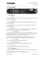
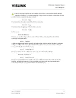
Selecting this button will return the menu screen to the main operating level from any point (as long 
as an item is not being edited). 

5.1.2.


E

SCAPE


Selecting this button will return the menu screen to the level above the one being displayed if an 
item is not being edited. 
 
If an item is being edited, then this button will cancel the change being made and return to the 
previously stored value. 

5.1.3.


S

TATUS


Selecting this button will change the menu screen to display the Alarms screen.  Pressing the button 
again will return the display to the screen that was previously being viewed. 

5.1.3.1.


A

LARM 

LED 

This LED will illuminate green when the system is operating as expected.  If the system is generating 
a warning, indicating that there is an issue to be aware of, the this LED will be illuminated in amber.  
If the system is generating an error, then the LED will be illuminated red. 
 
Details of the errors and warnings will be displayed in the Alarms screen, and which items are 
displayed as alarms and their severity may be configured using the internal web interface. 

5.1.3.2.


P

OWER 

LED 

This LED will be illuminated green when power is applied to the unit. 

5.1.4.


N

AVIGATION 

(

˄ ˅ ˂ ˃

These buttons are used to navigate up, down, left and right around the menu screens. 

5.1.5.


E

NTER


When editing an item this button will apply and store the selected value. 

5.2.


Menu Screen 

The menu screen provides the facility to configure all aspects of the unit via the front panel buttons. 
 
See Menu Navigation (section 8 below) for full details of the menus. 

Summary of Contents for UltraDecoder

Page 1: ...ngdom Telephone 44 0 1442 431300 Facsimile 44 0 1442 431301 Email sales vislink com Website www vislink com Company Registered in England no 1910243 VAT registration no 448 636 222 Registered Office Marlborough House Charnham Lane Hungerford Berkshire RG17 0EY UltraDecoder OPERATORS MANUAL ...

Page 2: ... Panel 11 6 1 IP Video 11 6 2 Ethernet Control 11 6 3 ASI In 12 6 4 Data 12 6 5 USB 12 6 6 Eth 1 12 6 7 Eth 2 13 6 8 ASI Out 13 6 9 3G SDI 13 6 10 4K HDMI 13 6 11 AC Power 13 7 IP Setup 14 7 1 Basic 14 7 2 Web Browser control 14 7 3 IP Video In 15 7 4 Complete Configuration 15 7 5 Decoder Communications Recovery Procedure 16 8 Menu Navigation 18 8 1 Decoder Setup 18 8 2 Unit Setup 20 8 3 System 24...

Page 3: ...he information contained in this manual remains the property of Vislink and may not be used disclosed or reproduced in any other form whatsoever without the prior written permission of Vislink Vislink reserves the right to alter the equipment and specification appertaining to the equipment described in this manual without notification ...

Page 4: ... History Version Date Modification Firmware Version Valid From or greater 1 26 11 2015 Initial release 2 14 12 2015 Added IP Setup and Decoder communications recovery procedure 3 21 12 2014 Added Read Me First Quick Start Guide and full Menu Tree Upgrade procedure modified Miscellaneous corrections AUTOBOOT P00016 Vt00 ...

Page 5: ...trol can be made either by SNMP or by accessing the internal web server from a web browser A clear graphical routing page in the web browser interface gives total control of all the possible combinations This common control page also contains links to all adjustable parameters of the unit at a single click This manual provides information on the complete range available note that not all options a...

Page 6: ...l using the supplied cables or by connecting all four to an external ethernet switch This is shown in more detail in Chapter 7 It is recommended that the initial configuration of the port addresses is done with the connections made directly using the supplied cables If the unit is to be connected to an external network with more than one UltraDecoder unit present then the default IP addresses of t...

Page 7: ...can then be similarly configured by selecting Menu Unit Setup IP Options IP Port Setup if the IP Video port and Eth 1 are to be connected to your network or can be left as default if a direct connection is to be used Note that if a direct connection is used between the IP Video and Eth 1 ports then the unit can only be used in ASI input mode The unit can now be powered off and supplied cables safe...

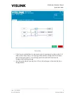
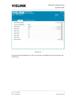
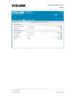
Page 8: ...essary to select a receiving port number on the IP IP Video In tab as shown below The receiving address will be as configured for the IP Video port in the previous section The unit being used to transmit the IP Video must be configured with matching settings Once the system detects incoming ASI or IP then a tick will appear in the status box top in the page header ...

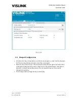
Page 9: ... the dropdown list if the incoming ASI stream contains more than one program Select the output video format The decoder will automatically recognise the format of the incoming ASI stream and will up scale or down scale to the selected format Note that it is important to select the same frame rate as the incoming ASI stream as this cannot be changed by the decoder If not already selected change the...

Page 10: ...perators Manual Quick Start Guide Issue 3 23 12 2015 6 Ref ULTD ASUM 7001 Copyright Vislink plc DECODER TAB Video should now be displayed if a monitor is connected to the HDMI All formats or SDI ports HD and SD only ...

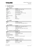
Page 11: ...eature Description IP Video 10 100 1000 Base T Ethernet ASI 75Ω to ISO IEC 13818 2 188 204Bytes constant rate 4 3 Outputs Feature Description ASI 75Ω to ISO IEC 13818 2 188 204Bytes constant rate IP Video 10 100 1000 Base T Ethernet HDMI 4K 4096 x 2160 or Ultra HD 3840 x 2160 HD or SD 3G SDI SMPTE 424M 4 4 Remote Control Monitoring Feature Description USB For software upgrades Remote Control 10 10...

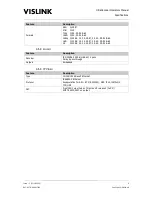
Page 12: ...94 60 UHD 23 98 24 25 29 97 30 50 59 94 60 4K 23 98 24 25 29 97 30 50 59 94 60 4 5 2 AUDIO Feature Description Decoder ISO 14496 3 2006 HE AAC 4 pairs Dolby E pass through Outputs Embedded 4 5 3 IP VIDEO Feature Description Type 10 100 1000 Base T Ethernet Protocol IEEE802 3 Ethernet Encapsulation for ASI RTP RFC2250 ARP IPv4 IGMPv2 3 TCP UDP FEC Pro MPEG Forum Code of Practice 3 release 2 CoP3 SM...

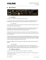
Page 13: ...1 ALARM LED This LED will illuminate green when the system is operating as expected If the system is generating a warning indicating that there is an issue to be aware of the this LED will be illuminated in amber If the system is generating an error then the LED will be illuminated red Details of the errors and warnings will be displayed in the Alarms screen and which items are displayed as alarms...

Page 14: ... Copyright Vislink plc 5 3 USB This connector provides the facility for upgrading the unit s software via a USB memory stick as well as downloading and uploading the unit configuration Please see Appendix A Upgrade Procedure section 10 1 below for details on how to perform an upgrade ...

Page 15: ...location using service names to extract the various services in the same manner as if it was a direct ASI connection To cross networks the IP video can be configured using the default gateway and sub net mask setup parameters and the protocol used may be set to either RTP or UDP via the Encap option Multicast is also supported and is enabled by configuring the Destination IP address to a value in ...

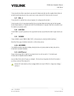
Page 16: ... this connector to provide a summary alarm status of the UltraCoder Normally this is configured at the factory for an open circuit indicating a fail This configuration may be reversed by the use of internal status link on the control PCB Parameters that can set the relay can be controlled via the web interface on the Alarm Mask page found under the Unit settings 6 4 3 PIN OUTS Pin Signal Descripti...

Page 17: ...via a network switch 6 8 ASI Out This 75Ω BNC is used to provide an ASI ouput which can be derived from the ASI In signal or ASI over IP 6 9 3G SDI These HD BNCs output 1080P 1080i 720P or SD via industry standard 3G SDI interfaces Note that this output is disabled when 4K or Ultra HD are active 6 10 4K HDMI The HDMI connector outputs 4K 4096 x 2160 4K Ultra HD UHD at 3840 x 2160 HD or SD to broad...

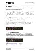
Page 18: ... to Also if changing from the default IP addresses whilst the unit is connected to a network ensure that only the decoder being configured is active as if other units are also connected their Eth 1 and Eth 2 addresses will be set to the values being assigned on the target unit 7 1 Basic In this mode the unit is configured for front panel control only and may only receive video via the ASI In conne...

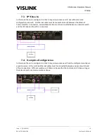
Page 19: ...ontrol and Eth 2 connectors and additional cables must be connected between a network switch and the IP Video and the Eth 1 connectors 7 4 Complete Configuration In this mode the unit is configured so that it may receive video over IP and be configure remotely via a web browser In this instance Ethernet cables must be connected between a network switch and all four connectors Different switches or...

Page 20: ...estore Defaults menu and set the IP Defaults option to Yes After about 20 seconds the unit will restart Once fully re started plug the memory stick in at the rear USB socket when the unit is already running Wait approximately 30 seconds the alarm light should go from red to green then remove the memory stick and power cycle the unit Wait for the unit to reboot and the Decoder Communications will b...

Page 21: ...UltraDecoder Operators Manual IP Setup Issue 3 23 12 2015 17 Ref ULTD ASUM 7001 Copyright Vislink plc ...

Page 22: ...1 1 VIDEO 8 1 1 1 PROGRAM NUMBER This item provides the facility to choose which service to decode by selecting the program number from a list of the current received values The list also includes an AUTO option which defaults the unit to always decoding the first program it receives 8 1 1 2 FORMAT This option is used to define the format of the output video The decoder will automatically recognis...

Page 23: ...Decoder Operators Manual Menu Navigation Issue 3 23 12 2015 19 Ref ULTD ASUM 7001 Copyright Vislink plc 8 1 2 AUDIO 8 1 2 1 AUDIO 1 4 PID These four items display the Audio PID being received by the decoder ...

Page 24: ...ut 8 2 1 IP OPTIONS These menus are used to configure the Video over IP settings 8 2 1 1 IP OUT 8 2 1 1 1 IP Video Out This menu provides the facility to configure the IP Video out 8 2 1 1 1 1 IP Output This selects the ASI signal source that can be streamed as IP Available options are Off or ASI In the physical rear panel connector 8 2 1 1 1 2 Destination IP This item defines the IPv4 Address to ...

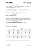
Page 25: ...P This setting configures the number of ASI packets to be encapsulated in a single IP Packet A lower number will result in less effect if an IP packet is lost but will result in a larger number of packets per second on the network Valid values range from one to seven 8 2 1 1 1 5 2 FEC This option provides the facility to enable or disable the forward error correction The following table gives some...

Page 26: ...the configuration settings for the video coming out of the unit to be supplied to the internal decoder via the Eth 1 connector and allows for the port number to be defined 8 2 1 1 2 1 IP Output This item displays the source being used for the video sent to the decoder 8 2 1 1 2 2 Destination IP This item displays the IPv4 address that the video is being sent to which will match the address of the ...

Page 27: ...sed to configure the source and format of the video output from the ASI Out connector on the rear panel 8 2 2 1 ASI OUT This option provides the facility to define the video output from the ASI Out connector Available settings are Off no ASI output ASI In ASI from the physical rear panel connector or IP In de encapsulated ASI from the IP Video input 8 2 2 2 ASI OUT MODE This option defines the siz...

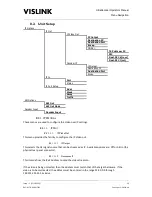
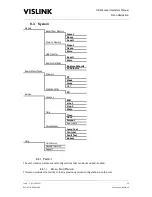
Page 28: ...faults IP Defaults Remote Interfaces Ethernet IP Mask Gway MAC Web Identifier ID Service Licences ESN Line 1 Line 2 State Time Time Date Format Run Hours Miscellaneous Lamp Test Contrast Fault Test Reboot Help Unit Version Decoder Version Support 8 3 1 PRESETS The unit contains sixteen preset configurations that can be saved and recalled 8 3 1 1 RECALL FROM MEMORY This menu provides the facility t...

Page 29: ... the selected Preset Note that the name will only be saved if the preset is saved to memory using the Store option 8 3 1 2 3 Store This option provides the facility to store the current unit settings to the selected Preset To perform the store select this item for editing change the value to Yes and press the Enter button The display will then change requesting confirmation of the action at which ...

Page 30: ...y defaults To perform this action change the setting to YES and then press the Enter button 8 3 2 REMOTE INTERFACES 8 3 2 1 ETHERNET This section provides the facility to configure the Ethernet settings for remote control by either SNMP or web browser 8 3 2 1 1 IP This item defines the IPv4 Address of the unit which will be used by external devices to connect to it via SNMP or web browser for remo...

Page 31: ...line displays the last fourteen characters of the unit s licence code If a new code is to be inserted it may be entered via this option however we recommend that the web interface is used for entering a new licence by copying and pasting as entering an incorrect licence may result in the unit becoming inoperable 8 3 3 1 4 State This item displays whether the licence code has been accepted by the u...

Page 32: ...splayed on the Alarm page which is accessed via the Status button 8 3 3 3 4 Reboot Selecting this option will initiate a reboot of the unit To perform this action change the setting to YES and then press the Enter button 8 3 4 HELP These menus provide information regarding the unit s software versions plus contact details should help from our customer support be required Please refer to the serial...

Page 33: ...he rear panel The command set is defined by the MIB To ensure the MIB is up to date a dedicated URL allows for the download of the MIB as a text file The URL is http ipaddrress common DVE5151 MIB txt case sensitive where ipaddress must be replaced with the actual IP address of the unit which can found under the System Remote Interfaces Ethernet menu The MIB may also be downloaded using the unit s ...

Page 34: ...irst accessed from your browser of choice features required by the interface will be checked and the status displayed Normally connection to the web interface would be achieved over a network however it is possible to directly connect a PC to the unit however note that the Ethernet cable would need to be of cross over type if the PC Ethernet port is not autosensing 9 2 1 OVERVIEW Status summary of...

Page 35: ... used when the Accept Changes button is selected The Accept Changes and Cancel Changes buttons will only be displayed if the configuration has changed Clicking on the switch boxes will step through the possible routing for that switch Clicking on the function link boxes will automatically change the display switching to the relevant page to configure the selected feature Note that only one switch ...

Page 36: ...opyright Vislink plc 9 2 2 ALARM LOGGING The Alarm Log tab is accessed under the Unit tab and on this page the most recent alarm events can be viewed with the information updating in real time Further options are provided to clear the events and to view and save the entire list of alarms ...

Page 37: ..._xxxxx is for the controller assembly front panel USB Procedure 1 Copy file 9261update xxxxx to a blank USB stick 2 Ensure the UltraDecoder is not on a network with other units connections ideally should be as shown here 3 Power on the unit to be up graded 4 Once fully started insert the memory stick into rear panel USB socket 5 After a few seconds the alarm light status led will turn red After ab...

Page 38: ...ms alarms by pressing the status key 12 On the front panel select system presets restore default IP defaults Yes 13 After about 20 seconds the unit will re start 14 On the front panel select system presets restore default Restore defaults Yes then power cycle the unit 15 Navigate to Unit Setup Menu IP Options IP Video output Decoder IP Setup Dest Port Press enter then enter again The unit has now ...

Page 39: ... an adequate airflow For the following fault conditions may occur suggested remedial action is described 10 2 1 CLOCK ERROR Replace internal back up battery refer to factory agent 10 2 2 OVER TEMPERATURE Check ventilation grilles on each side of unit are free of obstructions Check fans are running refer to factory agent for spares 10 2 3 DECODER FAULT Restart unit if continues refer to factory age...

Page 40: ...UltraDecoder Operators Manual Appendices Issue 3 23 12 2015 36 Ref ULTD ASUM 7001 Copyright Vislink plc 10 3 Appendix C Declarations of Conformity 10 3 1 EC DECLARATION OF CONFORMITY ...

Page 41: ...t the interference by one or more of the following measures Reorient or relocate the receiving antenna Increase the separation between the equipment and receiver Connect the equipment into an outlet on a circuit different from that to which the receiver is connected Consult the dealer or an experienced radio TV technician for help Properly shielded and grounded cables and connectors must be used t...

Page 42: ...O IN IP DATA IP PORT SETUP IP VIDEO OUT Decoder Ip Setup Ip Output MORE Dest Encap Dest Port TS PKTS per IP Ip Output Dest Encap Dest Port Addr Mask Traffic Gway ASI Out ASI Out Mode Decoder Input VIDEO AUDIO DE SCRAMBLING Program Number Format Restart decoder Audio 1 PID Audio 2 PID Audio 4 PID Audio 3 PID De scrambling Type Key IP VIDEO OUT Ip Dat PID Ip Data Output Allocate Port Status Fec cont...

Page 43: ...ECALL FROM MEMORY STORE TO MEMORY USB TRANSFER Name Preset Recall Store to USB Recall from USB TIME ETHERNET WEB IDENTIFIER Restore Defults Mask IP Gway MAC Web Identifier SERVICE HELP Name Preset Store LICENCES MISCELLANEOUS Line 1 ESN Line 2 State Date Time Format Run Hours Contrast Lamp test Fault Test Reboot DECODER VERSION UNIT VERSION SUPPORT ...

Reviews: