UltraDecoder Operators Manual
IP Setup
Issue : 3 (23/12/2015)
14
Ref : ULTD-ASUM-7001
Copyright © Vislink plc
7.
IP Setup
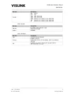
The four Ethernet connections on the rear panel must be configured to one of the following four
variants in order to ensure correct operation of the unit.
Note that when configuring the IP addresses for the unit, Eth. 1 and Eth. 2 are automatically
allocated addresses based on those used for the IP Video and Ethernet Control, as their addresses
plus one. For example, if IP Video is set to 192.168.2.6, Eth. 1 will be automatically set to
192.168.0.7. Therefore, never assign consecutive address values to IP Video and Ethernet Control,
and ensure that the addresses plus one do not cause a conflict on any network the unit is connected
to.
Also, if changing from the default IP addresses whilst the unit is connected to a network, ensure that
only the decoder being configured is active as, if other units are also connected, their Eth. 1 and Eth.
2 addresses will be set to the values being assigned on the target unit.
7.1.
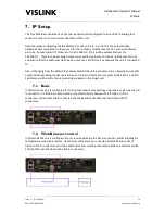
Basic
In this mode the unit is configured for front panel control only and may only receive video via the ASI
In connector. An Ethernet cable must be connected directly between the IP Video to Eth. 1
connectors and another cable connected directly between the Ethernet Control and Eth. 2
connectors.
7.2.
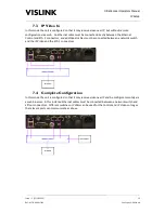
Web Browser control
In this mode the unit is configured to only receive video via the ASI In connector, whilst allowing for
configuration via a web browser. An Ethernet cable must be connected directly between the IP
Video to Eth. 1 connectors, and two additional cables must be connected between a network switch
and the Ethernet Control and the Eth. 2 connectors.

