UltraDecoder Operators Manual
Menu Navigation
Issue : 3 (23/12/2015)
23
Ref : ULTD-ASUM-7001
Copyright © Vislink plc
When modifying this option the IPv4 address for the Eth. 1 connector will automatically be
changed to this value + 1. Before attempting to adjust this value ensure that Ethernet Control
and Eth. 2 are connected to the same network.
8.2.1.3.2.
Mask
This item defines the subnet mask of the IP Video connector.
8.2.1.3.3.
Gway
This item defines the gateway of the IP Video connector.
8.2.1.3.4.
Traffic
For future use.
8.2.2.
ASI
O
PTIONS
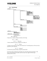
This menu is used to configure the source and format of the video output from the ASI Out
connector on the rear panel.
8.2.2.1.
ASI
O
UT
This option provides the facility to define the video output from the ASI Out connector. Available
settings are: Off (no ASI output), ASI In (ASI from the physical rear panel connector) or IP In (de-
encapsulated ASI from the IP Video input).
8.2.2.2.
ASI
O
UT
M
ODE
This option defines the size of the ASI packets output as either 188 or 204 Bytes.
8.2.3.
D
ECODER
I
NPUT
8.2.3.1.
D
ECODER
I
NPUT
This option provides the facility to define the source of the ASI stream that will be input to the
decoder. Available settings are: Off (no ASI output), ASI In (ASI from the physical rear panel
connector) or IP In (de-encapsulated ASI from the IP Video input).

