Barcode reader VB34
Installation
Da
te
of
issue
06/
1
3
/2005
26
Subject to reasonable modifications due to technical advances.
Copyright Fuchs, Printed in Germany
Fuchs Group • Tel.: G49 621 776-0 • USA +1 330 4253555 • Sin65 67799091 • Internet http://www.pepperl-fuchs.com
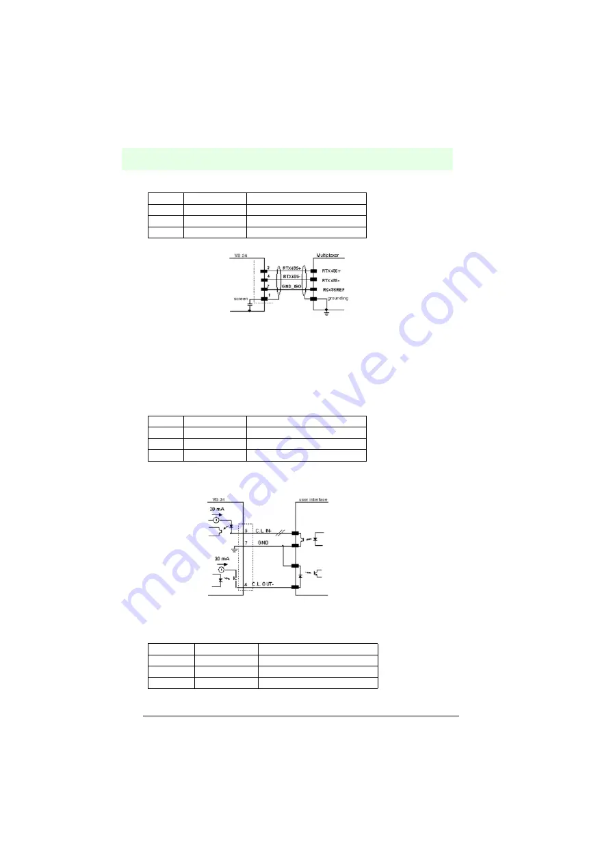
Figure 6.14
Connection layout of the RS485 interface (half duplex)
20 mA current loop (only with INT-60 accessory option)
If the INT-60 accessory card is installed, the VB34 has a 20 mA current loop as the
interface. The INT-60 card supports the operation as passive or as active current loop,
i.e. as sink or source.
Wiring as source
In the case of an operation as source, the 26-pin connector is wired as follows:
**
For 20 mA current loop, GND lies on the ground potential of the
reader voltage supply.
Figure 6.15
20 mA current loop, wiring as source (active)
If the VB34 reader is connected to a C-BOX 100 via a CAB-61X0, the signals are
connected to the following terminals of the C-BOX 100:
Pin
Description
Function
2
RS485 input/output (+)
4
RTX485-
RS485 input/output (-)
7
GND_ISO
Signal ground
Pin
Description
Function
4
CLOUT-
Current loop output (-)
5
CLIN-
Current loop input (-)
7
GND
Grounding*
Pin
Description
Function
12, 16
CLOUT-
Current loop output (-)
5
CLIN-
Current loop input (-)
10, 14, 19
GND
Grounding*


