


Barcode reader VB34
Installation
Da
te
of
issue
06/
1
3
/2005
39
Subject to reasonable modifications due to technical advances.
Copyright Fuchs, Printed in Germany
Fuchs Group • Tel.: G49 621 776-0 • USA +1 330 4253555 • Sin65 67799091 • Internet http://www.pepperl-fuchs.com
6.4
Operator interface
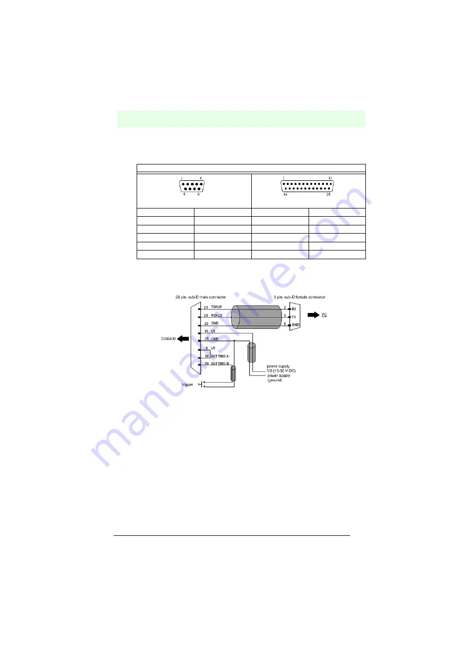
How to set up a simple test cable:
The following figure shows a simple test cable with supply, an external trigger (push
button) and the connection of the RS232 interface to a PC.
Figure 6.40
VB34 test cable
6.5
Adjusting the reader
The VB34 reader is able to read labels at most angles, however, a strong distortion
can have an unfavourable effect on reading performance.
When assembling the VB34, note the following three ideal angles for the label
position:
Tilt angle 0°, angle of rotation 10° to 30° and rotation 0°.
Follow the proposals in the next paragraph how best to position the reader:
The tilt angle is represented by the value P, see figure 41. Adjust the reader in such
a way that the tilt angle is held as low as possible.
RS232 connection assignment to the PC
9-pin connector
25-pin connector
Pin
Description
Pin
Description
2
RX
3
RX
3
TX
2
TX
5
GND
7
GND
7
RTS
4
RTS
8
CTS
5
CTS


