Barcode reader VB34
Installation
Da
te
of
issue
06/
1
3
/2005
42
Subject to reasonable modifications due to technical advances.
Copyright Fuchs, Printed in Germany
Fuchs Group • Tel.: G49 621 776-0 • USA +1 330 4253555 • Sin65 67799091 • Internet http://www.pepperl-fuchs.com
6.7
Typical hardware configurations
The following sections show typical examples for the system hardware configurations,
for which a corresponding software configuration is required. For more detailed
information, please refer to Chapter 7.2.
For other hardware configurations, a VB34 reader with a special decoder base
assembly may be required.
The illustrated cable and accessories are original products. To ensure the functional
capability and smooth operability of the system, it is recommended that you only use
these products.
6.7.1
Point-to-point
In a point-to-point arrangement, the data is transmitted both via the primary and
secondary interface. The primary interface can be adjusted to the full-duplex
communication in accordance with the RS232 or RS485 standard.
Depending on the VB34 model, various hardware configurations are possible.
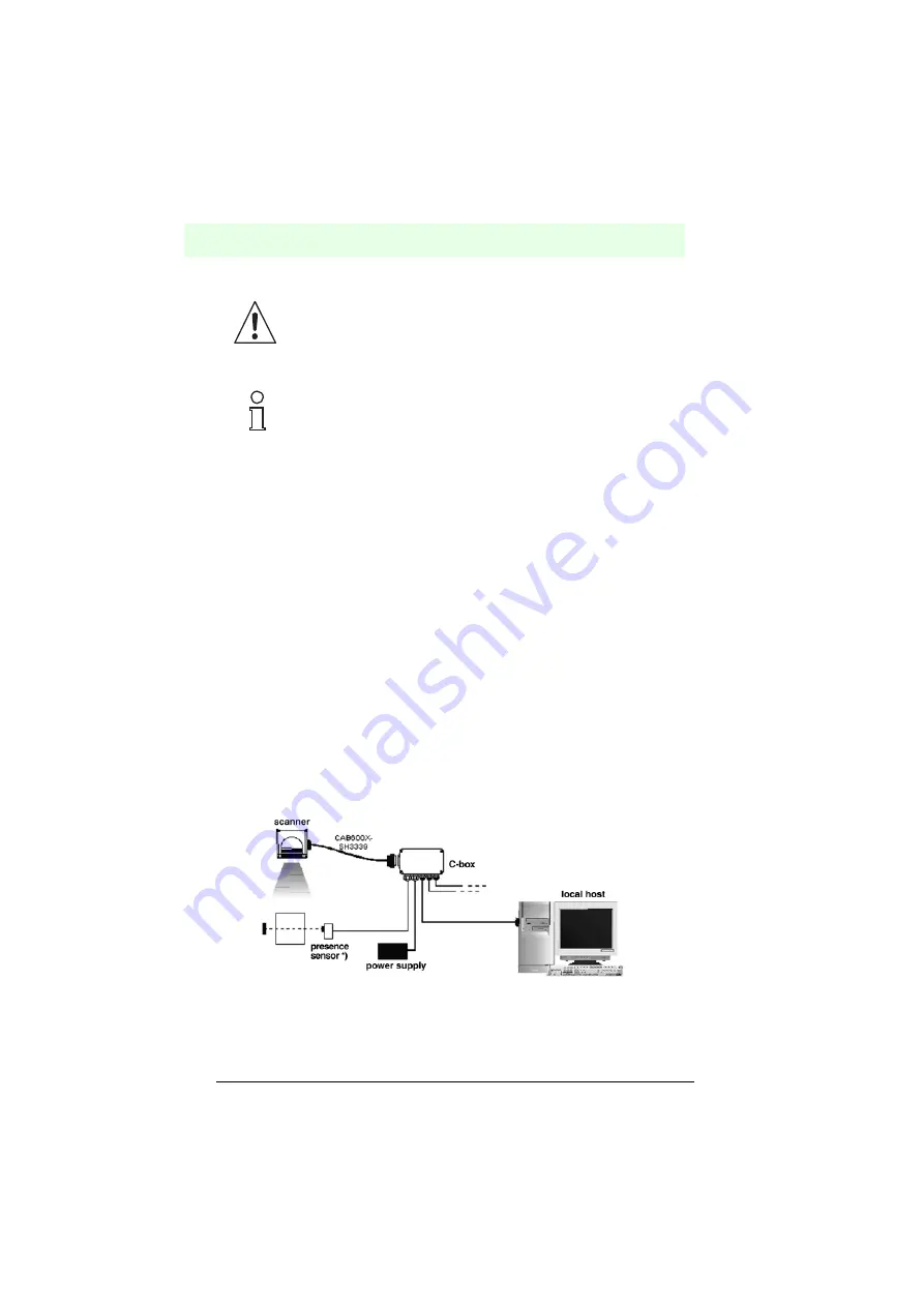
Master/slave models
During online operation, the reader is activated by an external trigger (light barrier)
when an object enters the reading zone. In the following example, the signal is
created via a C-BOX 100 to the VB34 reader, which also supplies the system.
*) Presence sensor connected to the external trigger input.
Figure 6.46
Point-to-point arrangement for master/slave models
With the installation with an angle of rotation of 45° it is not ensured
that the reader will achieve the same efficiency (see reading fields in
Figure 8.3.1) as in the standard installation with angles of rotation
between 10° and 20°.
The mounting angle ST-210 is contained as an accessory for the
VB34 standard model in the US-60 set.
Attention
Note


