Barcode reader VB34
Installation
Da
te
of
issue
06/
1
3
/2005
47
Subject to reasonable modifications due to technical advances.
Copyright Fuchs, Printed in Germany
Fuchs Group • Tel.: G49 621 776-0 • USA +1 330 4253555 • Sin65 67799091 • Internet http://www.pepperl-fuchs.com
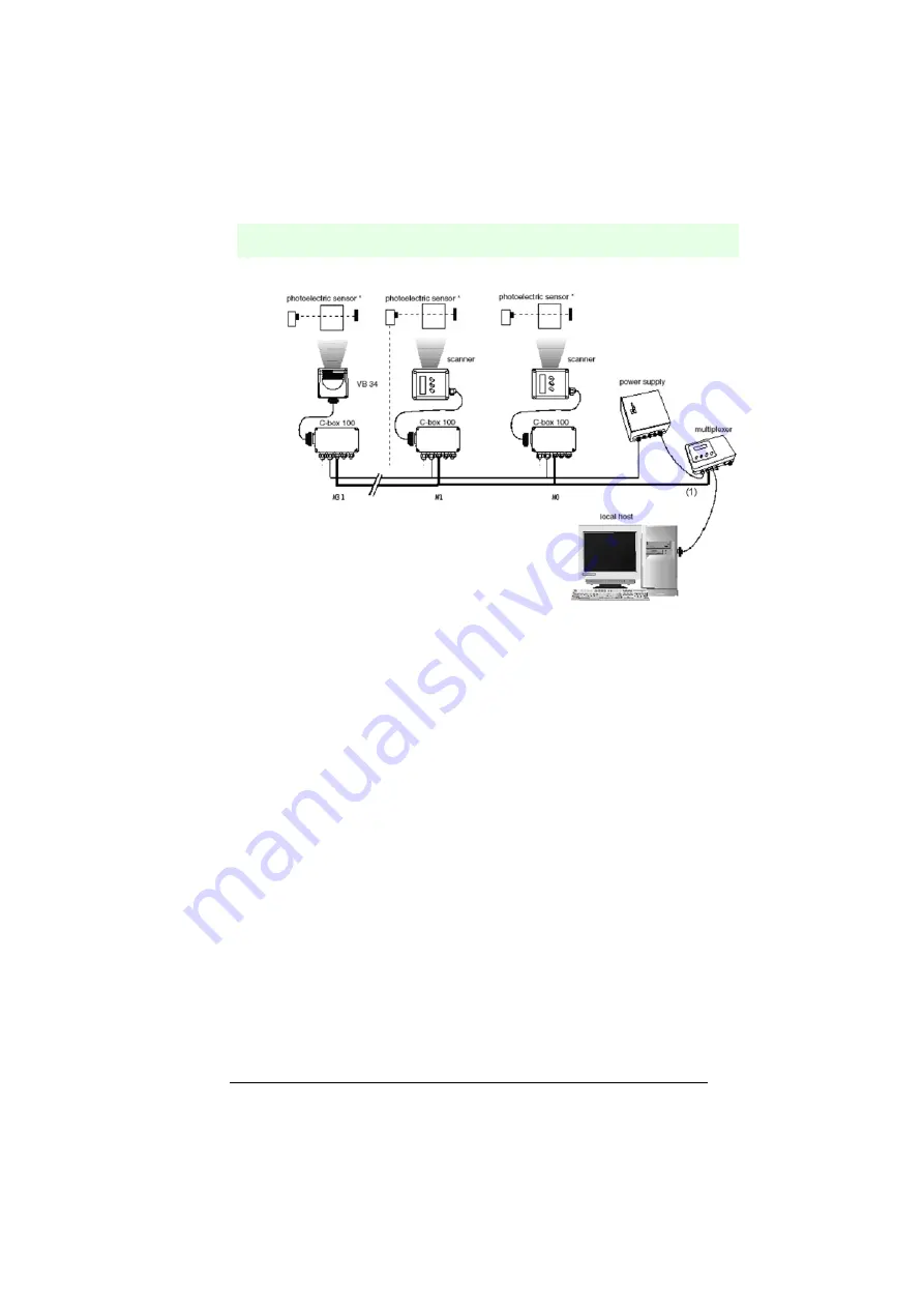
*) Light barrier (presence sensor) connected to the external trigger input .
(1) Primary serial interface
Figure 6.52
Multiplexer for VB34 master/slave models
The secondary serial interface of the slave readers can be used to visualize the
entered data or to configure via the configuration software.
During online operation, the reader is activated by an external trigger (light barrier)
when an object enters the reading zone.
6.7.5
Local Lonworks network
In a local Lonworks network, up to 31 VB34 slave devices can be connected to a
VB34 master reader. In real terms, the number of readers that can be used in the
network depends on the system operating conditions, especially on the operating
mode and the volume of data. The online operating mode (for additional information,
see the configuration software online help) supports, for example, a maximum of 8
slave readers.
With regard to the design of your network, always consider the following points:
• from an electrical point of view, the network supports up to 31 VB34 readers with a
network length of 130 m.
• the maximum number of supported VB34 readers depends on how the system
components are supplied. (For additional information, refer to Chapter 6.3.6.)
Contact VISOLUX if you have to integrate a large number of readers into your network
or if the data throughput in the application is extremely high.
When you construct the network, the VB34 master reader must be connected via the
25-pin Sub-D connector to a local computer or to C-BOX 100.
The first slave reader of the system is connected to the 9-pin Lonworks socket of the
master, while the 9-pin Lonworks connector must be completed with a BTK-6000
termination network.