Barcode reader VB34
Installation
Da
te
of
issue
06/
1
3
/2005
50
Subject to reasonable modifications due to technical advances.
Copyright Fuchs, Printed in Germany
Fuchs Group • Tel.: G49 621 776-0 • USA +1 330 4253555 • Sin65 67799091 • Internet http://www.pepperl-fuchs.com
Multiple light barrier (configuration available shortly).
In this layout, up to 7 VB34 slave readers each have a separate light barrier and thus
several read cycles. The light barrier, which controls the master reader, is connected
via the C-BOX 100.
The master transmits all the messages received via the Multidrop lead as well as its
own messages to the C-BOX 100, which forwards them to the local host.
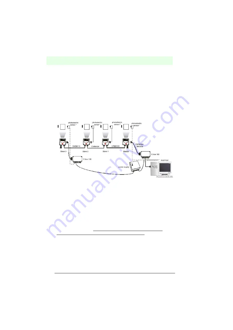
The following figure shows a system with four readers, in which the fourth reader is
supplied via a separate C-BOX 100 because a C-BOX 100 can supply a maximum of
3 readers. Therefore, the cable connecting the two separate groups does not carry
over the supply. In this example, this is cable CAB611X between slave 2 and slave 3.
*) Light barrier (presence sensor) connected to the external trigger input .
Figure 6.56
Multiple light barrier with more than 3 readers
6.7.6
Fieldbus network
Fieldbus models (Ethernet, Profibus and DeviceNet) enable communication in
fieldbus environments without a converter or adapter.
The VB34 fieldbus master communicates with the external host via a cable, which is
connected to the fieldbus connector (Ethernet, Profibus or DeviceNet). This host can,
for example, be an external PC with an IP address.
The 9-pin Lonworks socket is used to connect the first slave device to the master,
while the 26 Sub-D connector is used to supply the master via a C-BOX 100.
The slave readers (VB34 master/slave models) are connected together via the
Lonworks connector plug. The network must be completed with a BTK-6000
termination network on the 9-pin socket of the last slave reader. No termination
network is required for the fieldbus master because the termination is already
integrated.


