Barcode reader VB34
Optical properties
Da
te
of
issue
06/
1
3
/2005
66
Subject to reasonable modifications due to technical advances.
Copyright Fuchs, Printed in Germany
Fuchs Group • Tel.: G49 621 776-0 • USA +1 330 4253555 • Sin65 67799091 • Internet http://www.pepperl-fuchs.com
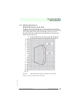
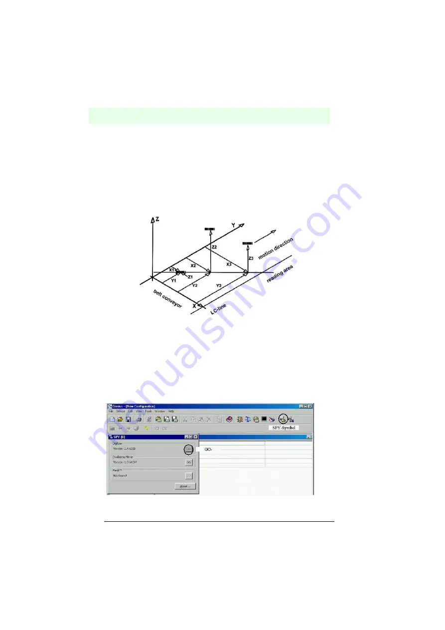
the reader to be able to recognize its own spacial position. This makes a fixed
reference system necessary.
The following figure shows this using a reference system which can be represented
using the right hand (thumb = X axis, index finger = Y axis and middle finger = Z axis),
where the Y axis corresponds with the direction of travel of the packets and the Z axis
runs vertically to the conveyor belt upwards (see the following figure). Three barcodes
are positioned in the scan line. Three coordinates are displayed for each of these
barcodes. (The X axis corresponds with the light barrier line).
Figure 8.6
PackTrack™ reference system
8.2.1
PackTrack™ calibration
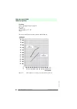
The reader can be calibrated via the configuration™ software.
Select the “SPY” option from the Tools menu or click on the corresponding symbol in
the configuration™ toolbar to show the following dialog field:
Figure 8.7
Opening the digitizer window
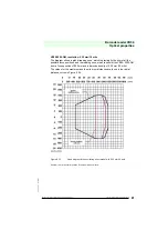
Absolute reference system
All the readers receive 5 pieces of infor-
mation via each barcode position: x, Y and Z (entered by the user) as well as the position in the scan line
and distance (measured from the reader)