Barcode reader VB34
Optical properties
Da
te
of
issue
06/
1
3
/2005
68
Subject to reasonable modifications due to technical advances.
Copyright Fuchs, Printed in Germany
Fuchs Group • Tel.: G49 621 776-0 • USA +1 330 4253555 • Sin65 67799091 • Internet http://www.pepperl-fuchs.com
8.3
Read diagrams
The read diagrams in the
following figures clarify the
conventions, which are
used in the calculation of
the minimum and
maximum distances for
reading barcodes. This
procedure makes it
possible to calculate the
reading distance for your
reader when using another
focus adjustment than that
specified in the read
diagrams in Chapter 8.3.1
and Chapter 8.3.2 .
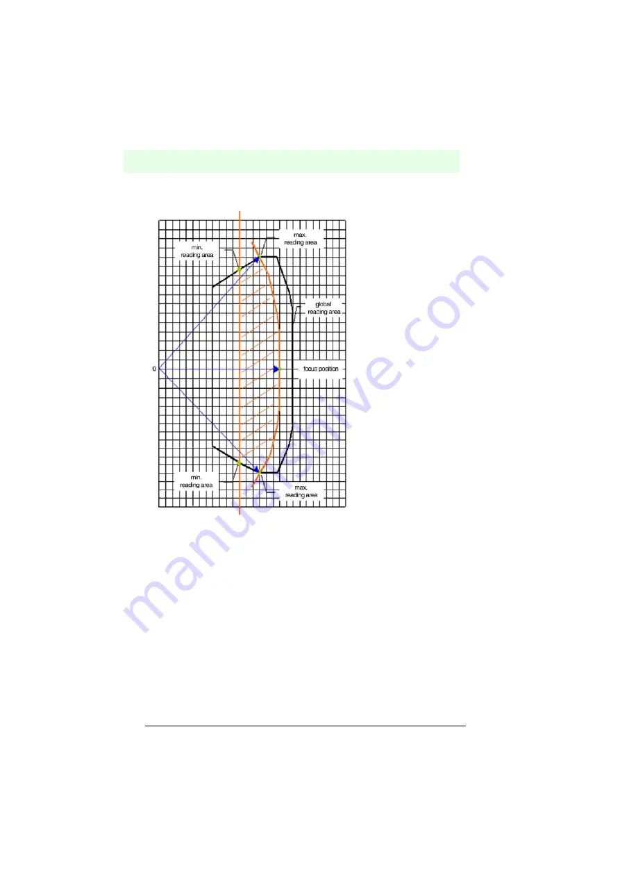
Mark the minimum focus
position with a straight
vertical line. The points of
intersection between this
line and the global reading
zone give the minimum
reading distance.
Figure 8.10
Calculating the reading zone
Mark the external outline of the global reading zone with the origin (0,0) and a radial
distance, which is equal to the maximum work distance of the reader. The points of
intersection between this outline and the global reading zone give the maximum
reading distance.
8.3.1
VB34 standard model
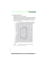
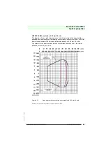
VB34-2500 (standard), resolution: 0,20 mm (8 mils)
The diagram shows a global reading zone, which is practically the sum of all the
possible focus positions, and the reading zone, which results for the VB34 from a
focus position of 650 mm and a barcode density of 0,20 mm (8 mils).
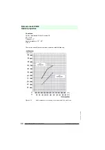
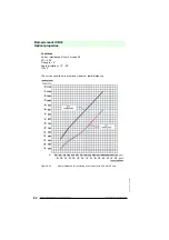
The values for the maximum and the minimum distances are found in the radial
distance curves in Figure 8.12.


