2
DE3580
3
33
3. INSTALLATION
. INSTALLATION
. INSTALLATION
. INSTALLATION
3.1 Installation Hints
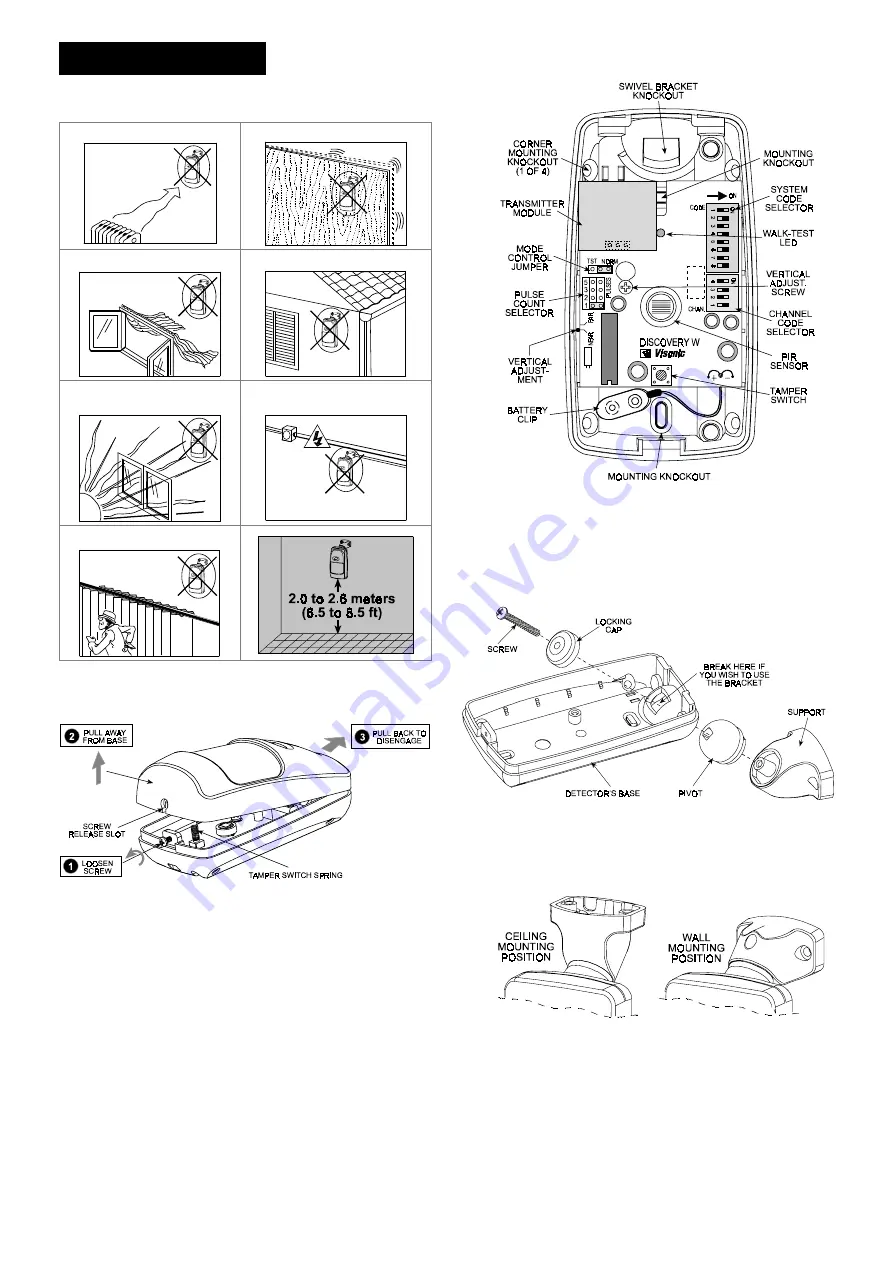
To minimize false alarms:
Do not aim at heat sources
Mount on solid, stable surfaces
Do not expose to air drafts
Do not install outdoors
Prevent direct sunlight from
reaching the detector
Keep wiring away from
electrical power cables
Do not install behind partitions
3.2 Mounting without Swivel Bracket
A .
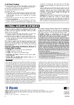
Remove the front cover as shown in Figure 3.
Figure 3.
Cover Removal
B .
Loosen the vertical adjustment screw, slide the PCB down
and remove it via the “keyhole” (see Figure 4).
C .
Pull the PCB straight out and put it aside until required again.
D .
Refer to Figure 4 and punch out the mounting knockouts at
the rear wall of the base (for surface mounting) or mounting
knockouts at the angled sides of the base (for corner
mounting).
E .
Hold the base against the wall at the selected installation
location and mark the points for drilling.
F .
Drill the holes and insert the plastic anchors supplied (if
necessary).
G .
Return the PCB to its place: align the ”keyhole” with the head
of the vertical adjustment screw, press the PCB against the
base, slide the PCB up and adjust it as explained in Para. 3.8.
Figure 4.
Inside View
3.3 Mounting with Swivel Bracket
A .
Remove the front cover as shown in Figure 3.
B .
Remove the PCB and put it temporarily aside.
C .
Punch out the large knockout in the round bulge at the top
part of the base (see Figure 5)
Figure 5.
Attaching the Bracket
D .
Assemble the bracket as shown in Figure 5.
E .
Rotate the bracket to the desired position (see Figure 6) but
do not yet tighten the screw fully.
Figure 6.
Wall and Ceiling Positions of Bracket
F .
Press the bracket against the mounting surface and mark the
points for drilling. Drill out the holes and insert plastic
anchors.
G .
Attach the bracket to the mounting surface using the two
screws supplied.


