D-303015 KP-140 PG2, KP-141 PG2 Installation Instructions
3
Step
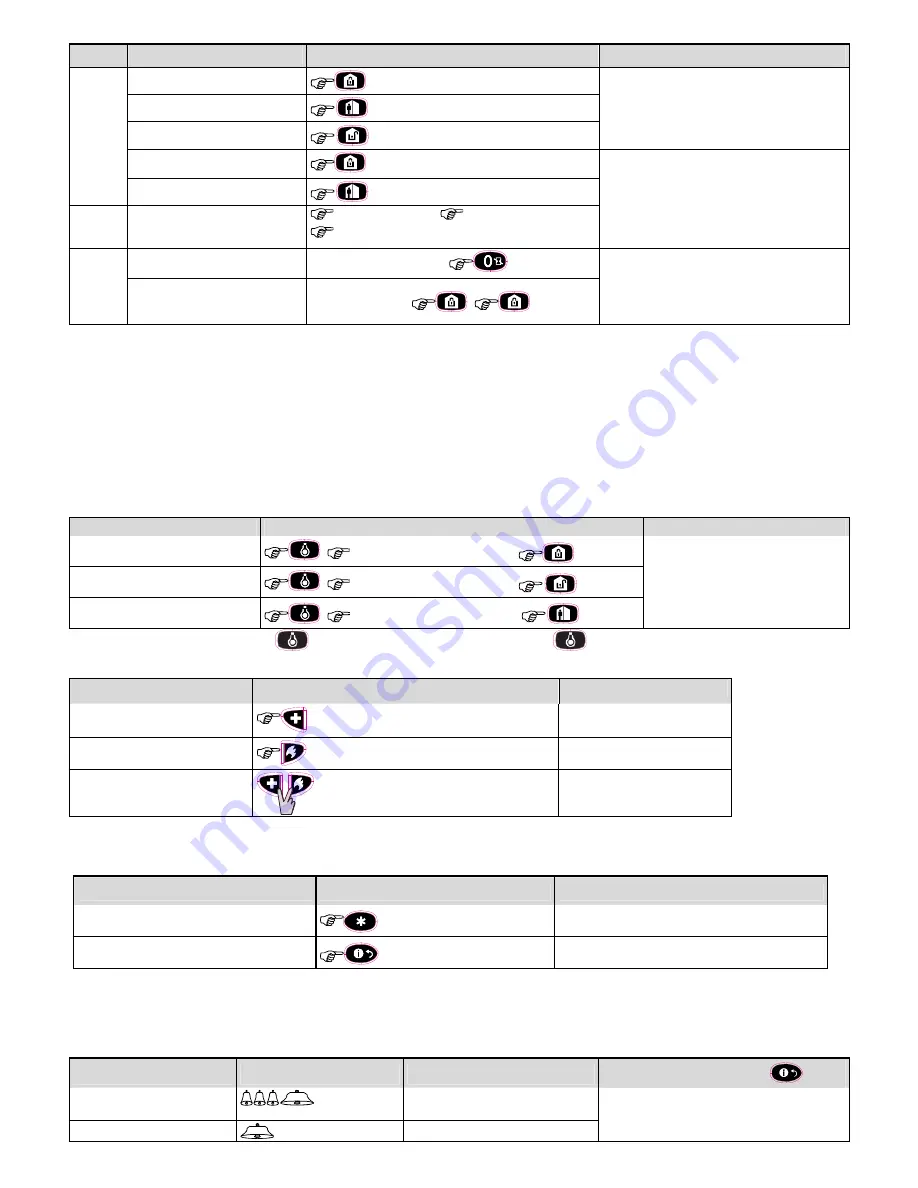
Basic Arming
User Actions
Keypad & Panel Response
2
Arm AWAY
The selected button starts blinking and prompts you
to enter your "User Code" or present your Tag. See
step 3.
Arm HOME
Disarm (OFF)
Quick arm AWAY
(2)
(
2 sec.)
The keypad's LED blinks red once to indicate
transmission of the arming command to the control
panel. The control panel's response is then
indicated on the keypad via the LED and the buzzer
– see
“Panel Response to Keypad Commands”
section 3.5 below.
Quick arm HOME
(2)
(
2 sec.)
3
Enter USER CODE or present
Proximity TAG.
(3) (4)
[USER CODE]
or
[
present
TAG]
[DURESS CODE]
(2580 by default)
(5)
4
INSTANT
(After arming HOME/ AWAY)
(6) (8)
The keypad's LED blinks red once to indicate
transmission of the command to the control panel.
The control panel's response is then indicated on
the keypad via the LED and the buzzer – see
“Panel Response to Keypad Commands”
in
section 3.5 below.
LATCHKEY
(After arming AWAY)
(7) (8)
Notes
:
1. If Partition is disabled at the control panel, skip Step 1.
2. The Quick arm functions only if enabled at the control panel.
3. If Quick arm is selected in Step 2, skip Step 3.
4.
(a) Pressing a non-valid code causes the control panel to reject the transmission.
(b) If the action is not completed while the selected arming button is blinking, the desired function will not be executed.
5. To use the Duress Code refer to the respective section in the control panel’s User Guide.
6. Press the INSTANT button within maximum 8 seconds timeout period after completing the previous step. This will delete the entry delay for the current arming session.
7. Press the AWAY button TWICE within maximum 8 seconds timeout period after completing the previous step. To use the LATCHKEY arming refer to the
respective section in the control panel’s User Guide.
8. You can perform the LATCHKEY and INSTANT functions, one after the other. The order is not important.
9. Latchkey Arming is supplemental in UL installations.
3.2 Automation
The functions of the PGM and X-10 outputs is configured at the corresponding sections of the control panel’s Installer Guide (see “OUTPUTS” menu) and User Guide
(see “SCHEDULER ” menu).
Note:
Automation not to be enabled in UL Listed Product.
Output Function
Actions
Response
X-10 or PGM device ON
[PGM
00
]
or [X-10
01 to 15
]
The keypad's LED blinks red once to
indicate transmission of the command to
the control panel. The control panel's
response is indicated on the keypad via
the LED and the buzzer – see
“Panel
Response to Keypad Commands”
in
section 3.5 below.
X-10 or PGM device OFF
[PGM
00
]
or [X-10
01 to 15
]
X-10 or PGM device TOGGLE
[PGM
00
]
or [X-10
01 to 15
]
Note:
Long press (more than 2 sec.) of the
button initiates the X-10 function. Short press of the
button initiates the PGM function.
3.3 Initiating Alarms
Alarm
Actions
Response
Emergency alarm
(
2 sec.)
See section 3.5.
Fire alarm
(
2 sec.)
See section 3.5.
Panic alarm
(
2 sec.)
See section 3.5.
Notes:
1.
For SIA CP01 compliance, the Emergency and Fire buttons are disabled. In case of Emergency or Fire, the two Panic alarm buttons should be used.
2.
For UL Listed product, Emergency is for ancillary use only.
3.4 Other Functions
Function
User Actions
Response
AUX Function
(1)
See section 3.5.
STATUS indication
See section 3.6
Note:
The function of the AUX button is configured in section 2.3 above
3.5 Panel Response to Keypad Commands
When executing a command, the keypad's LED ("M" in Figure 1) blinks red once to indicate transmission of the command to the control panel. If the operation is
successfully completed
, the green LED lights momentarily and a
"happy tune"
is heard. If the operation
fails or cannot be completed
, for example, when the
system is "not ready", the red LED lights steadily and a
"sad tune"
is heard. If a trouble or alarm memory condition exists in the system, or when the system is not-
ready to arm, the Status button (G in Figure 1) flashes for several seconds prompting you to press it to retrieve the status information from the control panel.
Panel Response
Buzzer Indication
LED Indication
Problem Indication
Success:
Operation is
successfully completed
Happy (
success
) beep
Momentary GREEN
If the panel is
Not-Ready
or if a
Trouble
or
Alarm
Memory
conditions exit, the Status button (G in Fig.1)
flashes for few seconds. To identify the reason, press
the button to retrieve the Status indication - refer to
Fail:
Operation
failed
Sad (
failure
) beep
Momentary RED


