background image

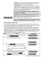
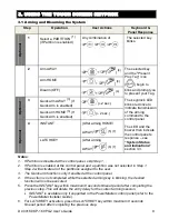
Arming and Disarming the System

Step

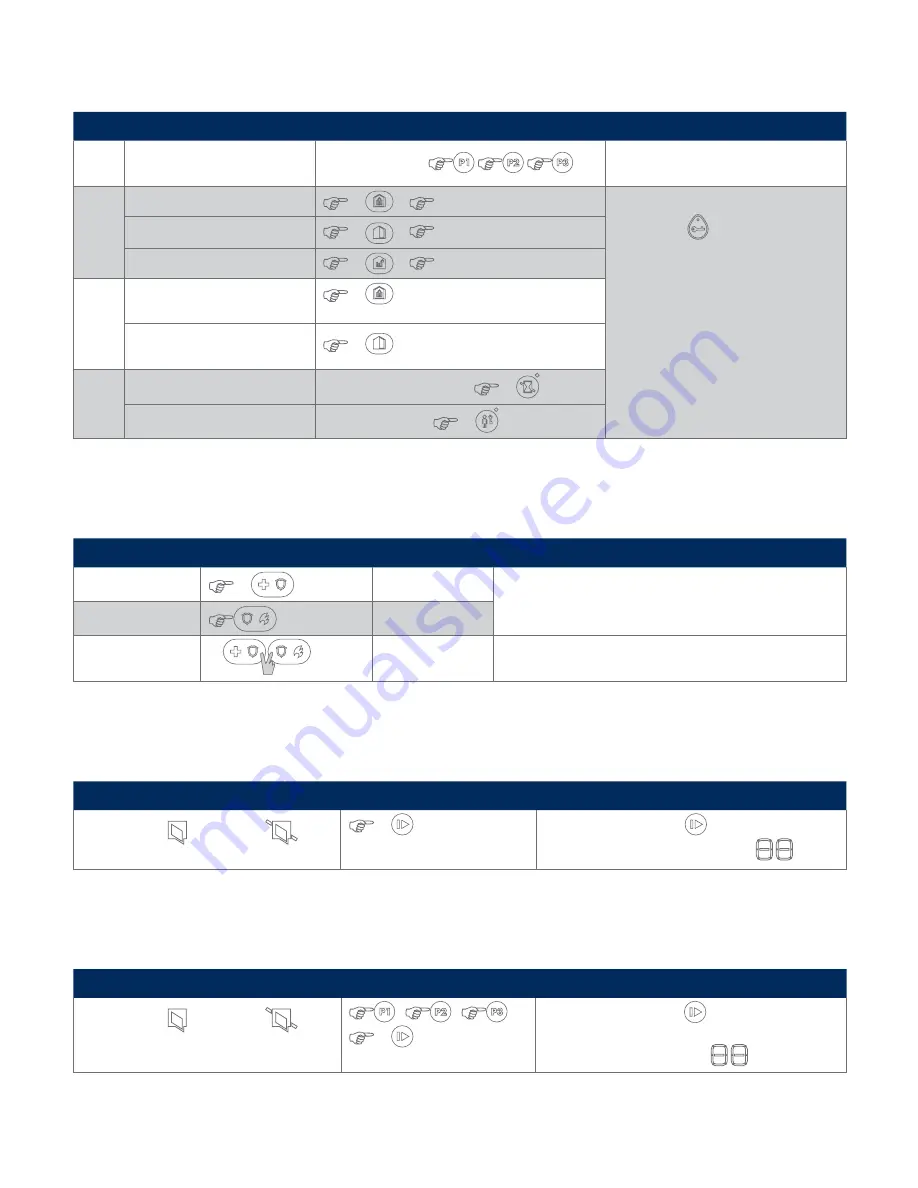
Basic Arming

User Actions

Keyboard & Panel Response

1

Select a PARTITION  
(if Partition is enabled)

Any combination of 


The selected key blinks.

2

Arm AWAY

 (3)

 + 

[present TAG] or [Enter code]

The selected key and the Present 

Prox Tag key (

) begin to blink and 

prompt you to present your tag or enter 
your code.
The Keypad’s LED blinks red once to 
indicate transmission of the arming 
command to the control panel. The LED 
and the buzzer then indicate the control 
panel’s response – see “System Status 
and Indications” section 3.3.

Arm HOME

 (2)

 + 

[present TAG] or [Enter code] 

Disarm (OFF)

 (1)

 + 

[present TAG] or [Enter code]

3

Quick arm AWAY (if Quick Arm 
is enabled)

 (3)

 (≈ 2 sec.)

Quick arm HOME (if Quick Arm 
is enabled)

 (2)

 (≈ 2 sec.) 

4

INSTANT

(After arming HOME/ AWAY) 

 (4)

LATCHKEY

(After arming AWAY) 

 (5)


Initiating Alarms

Alarms

Actions

Response

Notes

Emergency alarm

 (0)

 (≈ 2 sec.) 

See section 3.2.

Shortly after pressing the Emergency or Fire icon, the KP-160 
PG2 emits beeps until the KP-160 PG2 sends the command.

Fire alarm

 (≈ 2 sec.) 

See section 3.2.

Panic alarm

(0)

(≈ 2 sec.)

See section 3.2.

Shortly after pressing the Panic icon, the KP-160 PG2 emits 
beeps until the KP-160 PG2 sends the command.

Zone Status

State of Detector

Actions

Notes

For NOT READY (

/

 BYPASSED (

)

 (8)

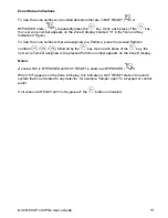
Upon each press of the (8)

 key, the next zone 

number appears on the Zone # display, 

.

Zone Status when working with Partitions

State of Detector

Actions

Notes

For NOT READY (

/

 BYPASSED (

)


/


/


 (8)


Upon each press of the (8)

 key, the next zone 

number assigned to the pressed Partition number 
appears on the Zone # display, 

.

Summary of Contents for KP-160 PG2

Page 1: ...www visonic com K e y p a d U s e r s G u i d e USER GUIDE K P 1 6 0 P G 2 ...

Page 2: ... DISARM 9 ARM HOME QUICK ARM HOME 10 ARM AWAY QUICK ARM AWAY 11 LATCHKEY 12 Mute exit beeps 13 Volume control 14 Show next status of open bypass zones 15 PGM X 10 16 INSTANT 17 FIRE 18 EMERGENCY 19 PANIC Press both keys simultaneously for 2 seconds 20 AUX Enroll KP 160 PG2 Back to factory Cancel current operation 21 Control panel messages 22 Installer Mode 23 Memory Alarm 24 Trouble 25 AC failure ...

Page 3: ...ing Options 4 2 4 Enrolling the KP 160 PG2 6 2 5 Configuring the KP 160 PG2 Parameters 6 2 6 Enrolling Proximity Tags 8 3 USING THE TOUCH SCREEN KEYPROX 9 3 1 Arming and Disarming the System 9 3 2 Initiating Alarms 10 3 3 System Status and Indications 10 3 4 Bypassing Zones 14 3 5 Controlling Home Automation Devices 14 3 6 Other Functions 15 APPENDIX A SPECIFICATIONS 15 APPENDIX B COMPLIANCE WITH ...

Page 4: ...gure The KP 160 PG2 can be wall mounted using the supplied bracket or be used as a portable unit For compliance with various international standards the KP 160 PG2 is equipped with two tamper switches that can be defined to detect when the cover of the battery compartment is removed or when the unit is removed from its mounting bracket Note For UL Listed Product unit is not intended to be portable...

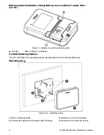
Page 5: ... an incorrect type Dispose of used battery according to manufacturer s instructions Figure 1 Battery Insertion Insert two 1 5V batteries in each slot while ensuring battery polarity 2 2 Closing Battery Compartment Cover Portable Installation Using Battery Cover without Tamper Hole 1 2 Figure 2 Battery Cover Mounting part a ...

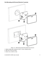
Page 6: ...r Mounting part b A Tamper B DC Power Connection 2 3 Wall Mounting Options The KP 160 PG2 unit mounting options are illustrated in the following drawings Wall Mounting Figure 4a Wall Mounting 1 Drill 3 mounting holes 3 Attach the unit to the bracket 2 Position the bracket and secure with 3 screws 4 Secure the unit with the screw ...

Page 7: ...all Mounting with External Electrical Connector Figure 4b Wall Mounting with External Electrical Connector 1 Secure bracket with 2 screws as shown in the two drawings above 2 Attach the unit to the bracket 3 Secure the unit with the screw ...

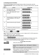
Page 8: ...lready enrolled you can configure the KP 160 PG2 parameters via the Modify Devices option see Step 2 2 5 Configuring the KP 160 PG2 Parameters Enter the main menu in the PowerMaster control panel choose the number of the touch screen keyprox device to configure and follow the configuration instructions for the KP 160 PG2 touch screen keyprox Option Configuration Instructions Define the active tamp...

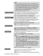
Page 9: ...OFF default and OFF night Note For UL Listed product set to ON Define the volume level of the sounder Option settings Medium default Maximum and Minimum Note For UL Listed product the sounder cannot be used as the only annunciator for the system Enabling the function will turn off the display if no key is pressed for more than several seconds Options settings Disabled default and Enabled Notes 1 W...

Page 10: ...rox as described below or through the PowerMaster control panel as described in the corresponding section of the control panel s User or Installer Guide Each proximity tag corresponds to its User Code Therefore be sure that a corresponding User Code is programmed for each enrolled proximity tag code 0000 is not allowed For example T02 Tag Prox must be assigned to User Code 2 and T14 Tag Prox must ...

Page 11: ...is enabled 2 sec Optional 4 INSTANT After arming HOME AWAY 5 7 LATCHKEY After arming AWAY 6 7 Notes 1 If Partition is disabled at the control panel skip Step 1 2 If Partition is enabled at the control panel and a partition was not selected in Step 1 Step 2 will activate all of the partitions assigned to the user 3 The Quick arm functions only if enabled at the control panel 4 If the action is not ...

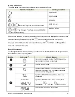
Page 12: ...conds the KP 160 PG2 sends the command Fire alarm 2 sec See section 3 3 Panic alarm 2 sec See section 3 3 When pressing the Fire and Emergency icons together the KP 160 PG2 starts beeping After pressing the button for approx 2 seconds the KP 160 PG2 sends the Panic command 3 3 System Status and Indications When executing a command the keyprox s LED 30 in the Icon and Key Indications Figure blinks ...

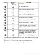
Page 13: ... is displayed concurrently with the second partition key LED and then the third partition indication is similarly displayed General Indications The Ready Not Ready Alarm Memory Trouble and Low Battery indications are provided via the indications in the following table Number Indication 1 What it Means Instructs the user to display the RFID proximity tag in order to initiate a command Volume contro...

Page 14: ...active trouble status that needs to be reviewed and cleared 3 AC failure Communication failure KP 160 PG2 is out of range of the control panel or did not get an acknowledge signal of a command from the control panel Indicates that the KP 160 PG2 device s battery is low and must be replaced see section 2 1 1 The key indication is displayed after the first red LED blinks indicating the status reques...

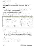
Page 15: ...mbers that are assigned to a Partition press the desired Partition number followed by the key Upon each press of the key the next zone number assigned to the pressed Partition number appears on the Zone display Notes A zone which is BYPASSED and NOT READY is shown as BYPASSED When 00 appears on the Zone display this indicates a NOT READY state in the alarm system that is not related to any detecto...

Page 16: ...PGM and X 10 output functions see the corresponding sections of the control panel s Installer Guide OUTPUTS menu and User Guide SCHEDULER menu Step X 10 device ON PGM device ON X 10 or PGM device OFF X 10 or PGM device TOGGLE 1 2sec 2 P0 to P9 00 to 99 PGM P0 to P9 or X 10 01 to 99 PGM P0 to P9 or X 10 01 to 99 3 Notes 1 Long press more than 2 sec of the button initiates the X 10 function and the ...

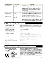
Page 17: ...Expectancy 4 years for typical use Low Battery Threshold 3 8 V Power source optional 5 12VDC Back light Blue white or black white Operating Temperature 0 C to 55 C 32 F to 131 F Note For UL Listed product the ambient temperature is 32 F to 120 F 0 C to 49 C Humidity Average relative humidity of approx 75 non condensing For 30 days per year relative humidity may vary from 85 to 95 non condensing No...

Page 18: ...smitter The portable device version complies with FCC and IC RF radiation exposure limits set forth for an uncontrolled environment The digital circuit of this device has been tested and found to comply with the limits for a Class B digital device pursuant to Part 15 of the FCC Rules These limits are designed to provide reasonable protection against harmful interference in residential installation...

Page 19: ... 3 2 sec Quick arm HOME if Quick Arm is enabled 2 2 sec 4 INSTANT After arming HOME AWAY 4 LATCHKEY After arming AWAY 5 Initiating Alarms Alarms Actions Response Notes Emergency alarm 0 2 sec See section 3 2 Shortly after pressing the Emergency or Fire icon the KP 160 PG2 emits beeps until the KP 160 PG2 sends the command Fire alarm 2 sec See section 3 2 Panic alarm 0 2 sec See section 3 2 Shortly...

Page 20: ... Security and Safety Needs U S E R G U I D E 2013 Visonic Ltd All rights reserved KP 160 PG2 Keypad English User Guide D 304456 Wireless PIR Pet immune Detector Proximity Tags Wireless Indoor Siren Wireless Fire Detector with Internal Siren Wireless PIR Camera Detector Wireless Curtain type Detector GSM GPRS Communicator Wireless Outdoor Siren ...

Reviews: