2
DE2462U
2. SPECIFICATIONS
ELECTRICAL
Battery Power Source:
Two 3 Volt Lithium batteries, type CR123A
(Sanyo or equivalent).
Battery Life Expectancy:
2 years (for typical use).
AC Power Supply (optional):
Plug-in transformer.
120 VAC, 60 Hz / 9 VAC, 0.35 A min. (in the U.S.A.)
230 VAC, 50 Hz / 9 VAC, 0.35 A min.
UL installation
: Use transformer type OH-35048AT, manufactured by
Oriental Hero Electrical Factory.
In Europe and elsewhere:
Use only Safety National Approved AC
adapter, mains-to-9 VAC, 0.35 A min.
AC Current Drain:
Approx. 30 mA standby, 300 mA max. at full load.
Display:
Single line, backlighted 16-character LCD and 4 LED indicators.
Control Functions:
Home Arming, Away Arming, Bypass, Disarming,
Latchkey, Light ON / OFF, Light Dim / Brightness, Recording, Forced
Arming, Panic, Fire and Emergency calls.
Sleep Mode:
Used to minimize current consumption. The unit enters
sleep mode 15 seconds after last use (applies only when using
batteries or when there is a power failure).
Supervision:
A periodic supervision message (programmable) is
transmitted automatically once every 15 minutes (Europe), once every
60 minutes (USA), or according to the local standards.
This function
can be disabled.
Panic Alarm Message
: Activated by simultaneously pressing the
and
keys.
Tamper Switch:
Normally closed. A tamper signal is transmitted in
three ways: when the MKP-150/MKP-151 case is opened; when the
keypad assembly is separated from the bracket; or if the MKP-
150/MKP-151 unit is ripped from the wall.
Compliance with Standards:
FCC part 15, EN 50131-1 Grade 2
Class II, TS 50131-3 and Directive 1999/5/EC
RF SECTION
Operating Frequencies:
315 MHz (in USA & Canada) or other UHF
channels per local requirement in the country of use.
Note:
At 315 MHZ the MKP-150 complies with UL 1023.
Receiver Type:
Super-heterodyne, fixed frequency
Receiver Range:
600 ft (180 m) in open space
Antenna Type:
Spatial
Coding:
Two-way wireless protocol
ENVIRONMENTAL
For indoor use only.
Operating Temp. Range:
0°C to 49°C (32°F to 120°F)
Storage Temp. Range:
-20°C to 60°C (-4°F to 140°F)
Humidity:
85% relative humidity, @ 30°C (86°F)
PHYSICAL
Dimensions:
172 x 99 x 39 mm (6 7/8 x 3 15/16 x 1 9/16 in.)
Weight:
375 g. (13 oz)
Mounting:
Surface-mounted
Color:
Light gray
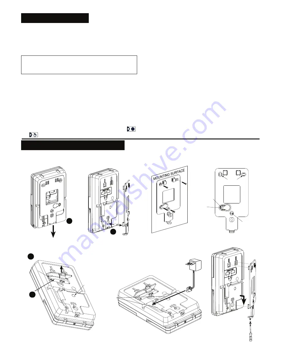
3. INSTALLTION AND WIRING
Perform the procedures as illustrated in the following Figures.
Note:
Mount the unit inside the secured premises, in a location providing optimum signal reception from the control panel unit, (refer to Installing
Wireless Systems Installation Guide – The Right Way, document no. DE2000W, for further details).
After removing
the screw,
pull down the
bracket fully
1
Remove
the bracket
2
Figure 2:
Bracket Removal
Mark and drill 4
holes in mounting
surface. Insert wall
anchors and fasten
the bracket to the
mounting surface
with 4 screws.
Screw
Holes
Screw
Hole
IMPORTANT !
The back tamper
switch will not
activate a tamper
alarm unless this
segment is secured
to the wall with
a screw.
Screw
Hole
Note:
Leave at least 3 cm (1.25 in.) free space around the bracket.
Figure 3:
Bracket Mounting
2
1
Press the tab inward
and remove the cover
Insert
batteries
(verify proper
polarity) and
close cover
Back
Tamper
Switch
Figure 4:
Battery Insertion
9
VAC
Wiring
Inlets
Connect the 9 VAC
power supply to the
terminal block. Route
the wiring through the
wiring channels.
Note:
The transformer
is optional
Figure 5:
Wiring
Match the panel with
the bracket projections.
Pull downward and
secure the bracket with
the locking screw
Figure 6:
Panel Mounting


