DE2462U MKP-150/151/152 User Guide
3
3. INSTALLATION AND WIRING
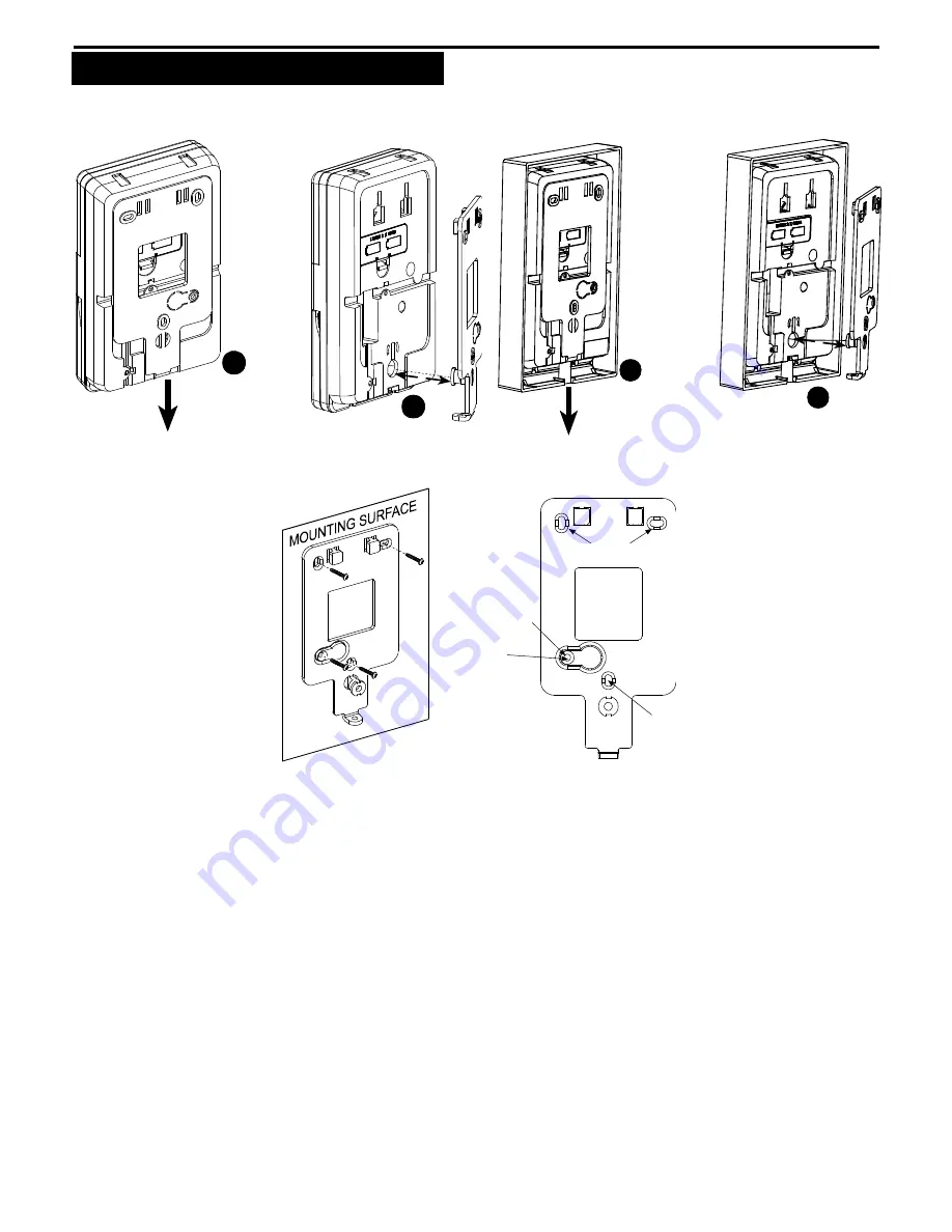
Perform the procedures as illustrated in the followingfigures.
Note:
Mount the unit inside the secured premises, in a location providing optimum signal reception from the control panel unit, (refer to Installing
Wireless Systems Installation Guide – The Right Way, document no. DE2000W, for further details).
After removing
the screw,
pull down the
bracket fully
1
Remove
the bracket
2
Figure 2a:
Bracket Removal – MKP-150/151
After removing
the screw,
pull down the
bracket fully
1
Remove
the bracket
2
Figure 2b:
Bracket Removal – MKP-152
Mark and drill 4
holes in mounting
surface. Insert wall
anchors and fasten
the bracket to the
mounting surface
with 4 screws.
Screw
Holes
Screw
Hole
IMPORTANT !
The back tamper
switch will not
activate a tamper
alarm unless this
segment is secured
to the wall with
a screw.
Screw
Hole
Note:
Leave at least 3 cm (1.25 in.) free space around the bracket.
Figure 3:
Bracket Mounting


